Index
Publication 1786-6.2.1 - April 1998
Symbols
A
abbreviations, 4
application considerations, 2-14
B
backup repeater, 2-6
barrel connector, 2-11, 2-18
BNC cable connectors, 1-4, 2-11
installing, 3-9
bridge, 1-1
bullet connector, 2-1, 2-11, 2-18
C
barrel, 2-11, 2-18
bullet, 2-11, 2-18
extender, 2-18
installing, 3-9
isolated bulkhead, 2-11, 2-18
rightangle, 2-11, 2-18
catalog numbers
1770KFC, 2-2
1784KTC, 2-2
1784KTCX, 2-2
1786BNC, 2-11, 2-18
1786BNCJ, 2-11, 2-18
1786BNCJI, 2-11, 2-18
1786BNCP, 2-11, 2-18, 3-2
1786CP, 2-2, 2-18, 3-19
1786CTK, 3-9, B-1
1786RPT, 2-6, 2-18
1786RPTD, 2-6, 2-18
1786TPR, 2-18
1786TPS, 2-18
1786TPYR, 2-18
1786TPYS, 2-18
1786XT, 1-4, 2-5, 2-18, 3-18
categories of conductors, 2-14
CE mark, 3-5
coax cable, 2-3
continuity tester, 3-14, 3-17
ControlNet cable system
application considerations, 2-14
attaching connectors to trunk ca-
ble, 3-15
cable connector
bullet, 2-1
cable connectors, 1-4, 2-11, 2-18
optional, 1-4
Coax Toolkit, 3-9
component definitions, 1-1
connecting cable sections, 3-18
connecting devices, 3-19
connecting programming termi-
nals through NAP, 3-19
determine
cable needed, 2-3
number of repeaters, 2-6
number of taps, 2-1
number of terminators needed,
trunkcable section lengths, 2-4
type of cable connectors need-
ed, 2-11
ferrite beads, 2-16
installing
cable connectors, 3-9
trunk cable, 3-1
link, 1-1, 1-5, 2-17
repeater configurations, 2-7
mounting taps, 3-2
network, 1-1
network access cable, 2-2, 2-18
node, 1-1, 1-2
ordering components, 2-17
planning guidelines, 2-17
redundant media, 2-12, 2-13
related publications, 5
repeater, 1-1, 1-5, 2-6, 2-18
connecting power and relay
circuitry, 3-7
connecting to a link, 3-21
grounding, 3-6
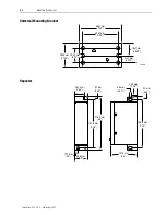
mounting dimensions, 3-6
segment, 1-1, 1-4, 2-17
stripping trunk cable, 3-10
surge suppression, 2-16
tap, 1-1, 1-3, 2-1, 2-18
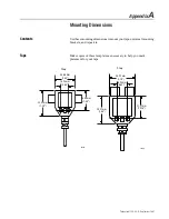
mounting dimensions, A-1
terminating segments, 3-18
terminator, 2-18
terminators, 1-1, 1-4, 2-5
testing for electrical continuity,
testing, 3-14, 3-17
wiring, 2-15
wiring external to enclosures,


