W 3 S E R I E S
H I G H P R E S S U R E A I R C O M P R E S S O R
©ALKIN COMPRESSORS
13
The intercoolers and the aftercooler are designed to dissipate the heat generated from the previous compression cycle,
reducing the air temperatures, allowing the water vapors to condensate and settle in the bottom sections of the
moisture separators. The 3 moisture separators and the pre-filter unit are equipped with an automatic drain valve.
The drain valve is a 3 way pneumatic valve controlled by a 3 way solenoid valve installe on the piping adjacent to the
centrifugal unloader. This solenoid valve sends or removes the control air from the drain valves, thus letting them to
open or close. The solenoid itself is controlled by a sequential timer relay in the electric panel. The dual time
adjustmens on this relay allows to adjust the duration (t1~ 15 min) during which the solenoid will remain energised
(=the drain valve will remain closed), and the length of time (t2~ 6 seconds) during which the solenoid will become
de-energised (=the drain valve will open and perform the drain function).
The compressor starts and stops with automatic regulation by a pressure switchgage (see sectionI-8 for adjustments
and functional details).
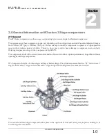
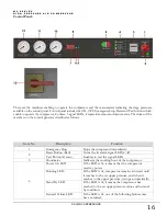
The oil level of can be monitored on a sight gage provided in the right bottom side of the crankcase (next to the Low
oil level switch) –see Figure 2. The oil level can also be checked through the dipstick found in the filling plug. In
principle the level of oil has to be up to the filling plug thread. A low oil level switch is provided to protect the
compressor from lack of oil in its sump. When the oil level drops, the switch cuts off (opens its contacts), thus cutting
the control circuit of the motor starter, and stops the electric motor. A signal lamp is provided to indicate that the
motor stopped as a result of low oil level.
2.4 Description of Major Components
2.4.1 Major Components - Compressor Unit
Crankcase:
This is the frame that holds everything on it. It contains the oil that lubricates the system. The cylinders are
mounted on it. The crankshaft is inserted into the bearing housings which is an integral part of the crankcase.
There is no maintenance or repair works that need to be done on this part; it needs to be cleaned inside when
the oil is changed. Due to its unique overhung design, the cleaning inside the crankcase is made possible as the
cover does not carry the bearing housings as in most other type compressors.
Crankshaft:
It is overhung type; that means the bearings are on one side, and the crank pin (where connecting rods are
mounted) are on the other side. This unique feature allows usage of single piece connecting rods which are far
more accurate and safe than split con rods. Large bearings in conjunction with low speeds, allow very long
crankshaft life.
Connecting Rods:
W3 model compressors have three rods
;
one main(middle) rod and two articulated rods. The piston at the
middle cylinder is connected the crack pin with main (middle) rod. Also main(middle) rod has a little stick
which enters the oil.
This stick in the bottom, enters the oil sump at every rotation, thus creating splash of oil
that lubricates the system. The all rods are constructed of investment cast steel alloy in H-shape, denoting the
cross-sectional shape. Bronze bushings are pressed into the bores in each end of the articulated rod to provide
knuckle-pin and piston-pin bearings. These journals wear in time and therefore the con rods will require
replacement or renewal of its bushings in due course.
Cylinders:
They are cast separately and are made of high grade casting materials, machined & honed to fined tolerances
for long service life. When worn, they will need replacement. The compression cylinders on the 3rd and 4th
stages are mounted on guide cylinder to guide the crosshead piston ass’y.
Head Assembly:
The head assemblies are the cover plates and the valve assemblies housed inside; these assemblies are mounted
on top of the cylinders. The valve assemblies inside the covers need to be maintained periodically; they need to
Summary of Contents for W3 Series
Page 1: ...W3 SERIES HIGH PRESSURE AIR COMPRESSORS...
Page 2: ......
Page 4: ......
Page 6: ......
Page 10: ...W 3 S E R I E S H I G H P R E S S U R E A I R C O M P R E S S O R ALKIN COMPRESSORS 5...
Page 14: ...W 3 S E R I E S H I G H P R E S S U R E A I R C O M P R E S S O R ALKIN COMPRESSORS 9...
Page 26: ...W 3 S E R I E S H I G H P R E S S U R E A I R C O M P R E S S O R ALKIN COMPRESSORS 21...
Page 30: ...W 3 S E R I E S H I G H P R E S S U R E A I R C O M P R E S S O R ALKIN COMPRESSORS 25...


