background image

W 3   S E R I E S  
H I G H   P R E S S U R E   A I R   C O M P R E S S O R  

©ALKIN COMPRESSORS 

19 

3.4 Electrical check  

Important! 

Al though all electrical instructions addressed to the reader directly, the actual inspection, 
wiring, installation, maintenance, repair etc. must be carried out by licensed and certified 

electricians

Make electrical connections to the compressor in accordance with the wiring diagrams and in full compliance 

with all applicable Federal, State and Local standards, codes and regulations, including those dealing with the 
grounding requirements. A few electrical checks should be made to insure that the first start up will be trouble 

free. Make the following checks before attempting any start up 

1.


Check the line voltage. Verify that the compressor motor corresponds to mains specifications. 

2.


Check the starter and overload for conformity with the motor power and current data. 

3.


Check all electrical connections for tightness, including those in the electrical panel of the compressor. 

4.


At start up, check the direction of rotation to insure flywheel rotating in the direction of the arrow on 

it.  Although  a  few  minutes  of  operation  in  the  wrong  direction  of  rotation  will  not  damage  the 

compressor, but running it this way in normal operation will create serious damage as the cooling air 
flow will be reversed, preventing the compressor cylinders to be cooled during operation. 


3.5 Wiring  

 It is important to select the right size wire and fuses. Install an isolation switch on the wall where the mains line is 
carried to, with magnetic protection and a capacity three times greater than the motor full load current. Use the same 

size wire between this unit and the compressor electrical panel. 


3.6 Sheaves and V-belt alignment check                                                                                                                                                                                            

Check the V-belt tension. Proper tension should be adjusted to give about 13 mm (

½

”) deflection with a 1 kg (2 

pnds) weight applied at the center of each belt. Check the condition of the belts periodically (see the maintenance 

table for details. 

3.7 Storage                                                                                                                                                                                           

If compressor will not be working for a long time for any reason and will be stored during this time, it is 

suggested to do the following steps before putting it out of reach in order to keep it in good condition:  

1.


Start the compressor and run it for app. 15 minutes.  

2.


Check if there is any leak on the fittings, hoses, tubes, filters and valves. 

3.


Open the filling valves and run it for app. 2 minutes at the min. pressure (the pressure which the priority 

valve is set at). 

4.


Open the drain valves and release the pressure inside the compressor. 

5.


After the unit is completely depressurised stop the compressor. Close the filling valves and drain. 

6.


Take out the refillable cartridge inside the purifier housing. 

7.


Remove the intake filter and disconnect all other connections on the valve heads. 

8.


Restart the compressor as soon as it cools down. Spray some compressor oil to the valve intakes and 

run the compressor for 2-3 minutes in this position. 

9.


Stop the unit before it gets too warm. 

10.


Connect the lines to the valve heads which are previously disconnected. 

11.


Close all the valves and put a cap onto the intake port against the dust and fumes may enter. 

Summary of Contents for W3 Series

Page 1: ...W3 SERIES HIGH PRESSURE AIR COMPRESSORS...

Page 2: ......

Page 3: ...W 3 S E R I E S H I G H P R E S S U R E A I R C O M P R E S S O R ALKIN COMPRESSORS 2 HIGH PRESSURE AIR COMPRESSORS W3 SERIES Instruction Manual Parts List Instruction Manual...

Page 4: ......

Page 5: ...r any parts thereof cannot be copied by any means or used for any other purposes other than servicing Alkin W3 series compressors unless specific permission of Alkin in writing is received ALKIN KOMPR...

Page 6: ......

Page 7: ...ment Diagram 12 2 3 Principles of Operation 12 2 4 Description of Major Components 13 2 4 1 Major Components Compressor Unit 13 2 4 2 Major Components System 14 2 5 Description of Controls 17 2 5 1 Co...

Page 8: ...placement 34 5 11 11 Radiator Intercoolers and aftercooler 34 5 11 14 Automatic drain valves 34 5 11 15 Filtration equipment 34 6 0 Trouble shooting 38 7 0 Parts list 42 4 1 Crankcase Assy 43 4 2 Conn...

Page 9: ...r compressors are well known with their faultless design and unique features combined with the best materials and workmanship Some of the most important features are centrifugal unloading regulators o...

Page 10: ...W 3 S E R I E S H I G H P R E S S U R E A I R C O M P R E S S O R ALKIN COMPRESSORS 5...

Page 11: ...cept with prior written approval of ALKIN 1 1 2 Pressure release Have the safety valves tested periodically by certified service personell and in conformity with the specific manufacturer s instructio...

Page 12: ...y when exposed to hot and or moving parts Make sure all persons are clear of the compressor prior to attempting to operate it Make adjustments only when the compressor is shut off When necessary make...

Page 13: ...pressor around If you must lift the compressor lift in full compliance with codes and regulations Make sure entire lifting rigging and supporting structure has been inspected is in good condition and...

Page 14: ...W 3 S E R I E S H I G H P R E S S U R E A I R C O M P R E S S O R ALKIN COMPRESSORS 9...

Page 15: ...t written approval of Alkin Failure to do so may result in heavy damage to equipment injury or death Working temperature range of the compressor is 0 45 C The compressor is built with oversize interco...

Page 16: ...easy to maintain and replace Particular attention must be paid to valve maintenance as these valves are the basis for proper operation of the compressor package Do not use oils other than the recomme...

Page 17: ...nd goes into the 2nd stage compression chamber Here the air is compressed to the 2nd stage compression level and forced through the 2nd stage valves 2nd stage intercooler 2nd stage water separator 3rd...

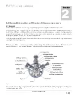
Page 18: ...rankcase This is the frame that holds everything on it It contains the oil that lubricates the system The cylinders are mounted on it The crankshaft is inserted into the bearing housings which is an i...

Page 19: ...essor s first stage Inner element of the intake filter should be replaced periodically according to the MAINTENANCE TABLE 2 4 2 Major Components System The Canopy The semi open canopy is designed to c...

Page 20: ...enters the purifier A refillable cartridge which contains the consumables performing the filtration is placed in the purifier housing Refillable cartridges are more cost effective and environtment fri...

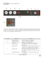
Page 21: ...escription Function 1 Emergency Stop Stops the compressor immediately 2 Reset Button Red Turns the lit alarm signal LED s off Test Button Green Enables to test the signal LEDs 3 Hourmeter Indicates th...

Page 22: ...iption of Controls 2 5 1 Compressor Controls The W3 Series compressor may operate with the following two controls Automatic Start Stop Control This is the standard control type for all single pressure...

Page 23: ...nstall the compressor on a level surface of sufficient strength to support the static weight of the equipment as well as the dynamic forces resulting form its operation preferably a 6 150 mm concrete...

Page 24: ...lation switch on the wall where the mains line is carried to with magnetic protection and a capacity three times greater than the motor full load current Use the same size wire between this unit and t...

Page 25: ...UT SHOULD BE COMPLETELY EMPTIED INNER SURFACE SHOULD BE CLEANED AND DRIED BY BLOWING AIR IN FAILURE TO DO SO MAY CAUSE THE PURIFIER CARTRIDGE GET PARTIALLY CONSUMED AND EVEN WASTED If the compressor w...

Page 26: ...W 3 S E R I E S H I G H P R E S S U R E A I R C O M P R E S S O R ALKIN COMPRESSORS 21...

Page 27: ...ection of the arrow on the compressor crankcase and flywheel 8 Press the start button to start the machine 9 Check for possible leaks in the piping 10 Close the filling valves on the filling panel and...

Page 28: ...er pressure In this case you may also need to change the safety valve as it is set to open when it reaches the upper pressure Turn the screw anticlockwise to decrease the upper pressure Compressor is...

Page 29: ...justments If required replace and return the old one for reconditioning to the factory or to a dealer nearest you Do not remove the leaking safety valves and do not replace it with a plug This may be...

Page 30: ...W 3 S E R I E S H I G H P R E S S U R E A I R C O M P R E S S O R ALKIN COMPRESSORS 25...


Page 31: ...Distributor Persons Attending the Commissioning Full Name Position In charge of Signature Equipment Details Model Serial Nr Date of purchase Date of comissioning Application Medium Air Gas specify PR...

Page 32: ...der stops venting when compressor runs Vibration Noise No back flow in the Check valve when the compressor stops V Hz Interstage and final safety valves not leaking Ambient Temperature C Crankcase oil...

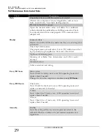
Page 33: ...wing are general guidelines for periodical maintanence specific details will be mentioned in the following chapters Use the Maintenance Table for maintenance and record keeping WARNING Before attempti...

Page 34: ...The proper tension should allow 13 mm deflection with a 1 kg 2 pounds weight applied on the center of each belt Tightness of fastening parts Cleaning of cylinder fins intercoolers and after cooler fly...

Page 35: ...filter element 1 Piece Every 1000 Hours 1 Piston rings 1 Set 2 Compressor valves 1 Set 3 Gasket Set 1 Set 4 O ring Set 1 Set 5 2nd stage water separator f lter element 1 Piece 6 Prefilter filter eleme...

Page 36: ...he two cover valves and between the head and the cylinders then replace the air head asembly Tighten the air head cap screws to the torque values recommended IMPORTANT Handle the valve parts with care...

Page 37: ...tortion Pay particular attention to install the rings with the marks facing the appropriate direction into the proper grooves 9 Work from bottom compression ring up on the top end of the piston and fr...

Page 38: ...f the necessary thickness between the rod and the boss must eliminate the play between the piston pin boss and the connecting rod 3 To install the new pin align the connecting rod between the bosses i...

Page 39: ...tened evenly and in rotation to the torque value given in the torque values table To avoid faulty valve operation the 2nd and 3rd stage air head attaching screws must be tightened as closely as possib...

Page 40: ...Turn the cover 5 and remove the whole assembly from the purifier chamber 5 Pull the cartridge 7 out of the purifier chamber 8 6 Open the flat end of the cartridge remove its contents Clean the inside...

Page 41: ...the tool used a makeshift tool that allaws further tightening wich may result in over pressing and crushing cartridge 12 Remove the tool 1 and the adapter 3 the installation of the cartridge is compl...

Page 42: ...W 3 S E R I E S H I G H P R E S S U R E B R E A T H I N G A I R C O M P R E S S O R ALKIN Kompres r Sanayi ve Ticaret Limited irketi 37...

Page 43: ...on if damaged replace damaged vib mounts can cause the baseplate to hit the base of canopy Loose motor fan Tigten if damaged replace Lack of oil in the crankcase a Check for possible damage to bearing...

Page 44: ...gap 6 7 COMPRESSOR VIBRATES Mounting bolts are loose Tighten the mounting bolts Compressor not properly mounted Level the compressor so that all feet touch the floor Motor sheave the flywheel misalig...

Page 45: ...Safety valve faulty Replace the safety valve Inlet valve of the next stage leaks Remove valves clean or replace Inlet valve of the next stage broken Remove valves clean or replace 6 13 CYLINDER PRESSU...

Page 46: ...wer regulation unbalanced phases Notify the power company 6 21UNUSUAL PISTON RING OR CYLINDER WEAR Imporper oil Replace with proper oil Low oil level Check level check why low oil level switch did not...

Page 47: ...W 3 S E R I E S H I G H P R E S S U R E B R E A T H I N G A I R C O M P R E S S O R ALKIN Kompres r Sanayi ve Ticaret Limited irketi 42 7 0 Parts list Parts List Section 7...

Page 48: ...W 3 S E R I E S H I G H P R E S S U R E B R E A T H I N G A I R C O M P R E S S O R ALKIN Kompres r Sanayi ve Ticaret Limited irketi 43 4 1 Crankcase Assy...

Page 49: ...6882 40 BOLT M10x55 6 1 16 7375 05 O RING 210x3 1 1 17 AYD 418 CRANK SPACER 1 1 18 AYD 419 CRANK SPACER 1 1 19 6937 87 BEARING FAG 2212NUP C3 1 1 20 AYD 220 CRANK SHAFT 1 1 21 AYD 420 CRANK COUNTER WH...

Page 50: ...W 3 S E R I E S H I G H P R E S S U R E B R E A T H I N G A I R C O M P R E S S O R ALKIN Kompres r Sanayi ve Ticaret Limited irketi 45 4 2 Connecting Rods...

Page 51: ...ER M10 1 2 04 AYD 415 WASHER 1 2 05 6937 86 BEARING NA 6910 1 2 06 7096 18 BOLT M6x10 6 2 07 7868 50 BOLT M8x15 2 2 08 AYD 171 PIN RETAINER 2 2 09 AYD 221 PIN 20x40 2 2 10 AYD 168 LUBRICATING STICK 1...

Page 52: ...W 3 S E R I E S H I G H P R E S S U R E B R E A T H I N G A I R C O M P R E S S O R ALKIN Kompres r Sanayi ve Ticaret Limited irketi 47 4 3 1st Stage Assy...

Page 53: ...R 160 1 3 08 3005 62 GASKET 1 3 09 AYD 449 VALVE ASSY 160 1 01 3006 48 BODY 160 1 02 3006 50 WASHER 50 4 03 3006 52 SPRING DISCHARGE 50 2 04 3006 51 SPRING INTAKE 50 2 05 3006 49 INSERT 50 4 06 3006 5...

Page 54: ...W 3 S E R I E S H I G H P R E S S U R E B R E A T H I N G A I R C O M P R E S S O R ALKIN Kompres r Sanayi ve Ticaret Limited irketi 49 4 4 2nd Stage Assy...

Page 55: ...2x35 4 4 14 2500 00 CYLINDER 69 85 1 4 15 7729 30 O RING 110 72x3 53 1 4 16 0449 01 CYLINDER COVER 1 4 17 8044 00 BUSHING 4 4 18 7096 64 BOLT M12x85 4 4 19 0631 00 WASHER CAGE VALVE 2 4 20 0453 00 VAL...

Page 56: ...W 3 S E R I E S H I G H P R E S S U R E B R E A T H I N G A I R C O M P R E S S O R ALKIN Kompres r Sanayi ve Ticaret Limited irketi 51 4 5 3rd Stage Assy...

Page 57: ...M6 2 5 10 7867 09 BOLT M6x20 2 5 11 7729 37 O RING 154x3 1 5 12 7091 07 WASHER M12 10 5 13 6884 41 NUT M12 4 5 14 0027 00 GUIDE CYLINDER 3 5 1 5 15 0054 00 GASKET 1 5 16 6481 01 CYLINDER 25 4 3 KD 1...

Page 58: ...W 3 S E R I E S H I G H P R E S S U R E B R E A T H I N G A I R C O M P R E S S O R ALKIN Kompres r Sanayi ve Ticaret Limited irketi 53 4 6 Pipe Lines 1st Stage...

Page 59: ...4 6 13 7867 55 BOLT M6x25 4 6 14 AYD 86 PLUG 3 4 1 6 15 AYD 71 NIPPLE 3 4 x 20 1 6 16 2000 18 TUBE 20 1 6 17 3004 76 ELBOW 20 1 6 18 AYD 542 UNION 3 4 xM30 1 6 19 AYD 17 RADIATOR 30 BAR 1 6 20 AYD 77...

Page 60: ...W 3 S E R I E S H I G H P R E S S U R E B R E A T H I N G A I R C O M P R E S S O R ALKIN Kompres r Sanayi ve Ticaret Limited irketi 55 4 7 Pipe Lines 2nd Stage...

Page 61: ...17 WASHER M6 2 7 15 6884 21 NUT M6 FIBERED 2 7 16 7070 05 CLAMP RETAINER 1 7 17 7091 62 WASHER M14 1 7 18 7091 61 SPRING WASHER M14 1 7 19 7867 50 BOLT M14x60 1 7 20 3024 42 SUPPORT 1 7 21 7696 03 PLU...

Page 62: ...W 3 S E R I E S H I G H P R E S S U R E B R E A T H I N G A I R C O M P R E S S O R ALKIN Kompres r Sanayi ve Ticaret Limited irketi 57 4 8 Pipe Lines 3rd Stage...

Page 63: ...30 1 8 07 7425 01 FITTING 1 4 x 10 2 8 08 7672 12 ELBOW 1 4 1 8 09 7055 38 WATER SEPARATOR 1 01 7055 41 TOP CAP 1 02 7983 01 MUFFLER 1 4 1 03 3005 28 O RING 42x3 2 04 7055 39 BODY 1 05 7055 40 BOTTOM...

Page 64: ...W 3 S E R I E S H I G H P R E S S U R E B R E A T H I N G A I R C O M P R E S S O R ALKIN Kompres r Sanayi ve Ticaret Limited irketi 59 4 9 Intercooler...

Page 65: ...Description Qty 9 00 3006 55 01 SO UTUCU 2 KD 1 9 01 3003 98 01 FINNED TUBE 6 9 02 3005 05 01 NIPPLE 1 9 03 3021 33 O RING 23x4 6 9 04 3020 54 O RING 32x3 12 9 05 3020 92 MANIFOLD 4 9 06 3021 15 PLUG...

Page 66: ...W 3 S E R I E S H I G H P R E S S U R E B R E A T H I N G A I R C O M P R E S S O R ALKIN Kompres r Sanayi ve Ticaret Limited irketi 61 4 10 Aftercooler...

Page 67: ...Qty 10 00 2000 20 02 AFTERCOOLER 1 10 01 2000 21 02 TUBE 1 10 02 7291 50 CLAMP 6 10 03 7091 17 WASHER M6 60 10 04 7867 60 BOLT M6x30 12 10 05 6884 21 NUT M6 FIBERED 30 10 06 7291 06 BRACKET 1 10 07 7...

Page 68: ...W 3 S E R I E S H I G H P R E S S U R E B R E A T H I N G A I R C O M P R E S S O R ALKIN Kompres r Sanayi ve Ticaret Limited irketi 63 4 11 Out Line...

Page 69: ...7145 02 NUT 5 8 8 MM 1 11 14 3007 43 ELBOW 3 8 x 10 1 11 15 2000 29 TUBE 10 1 11 16 7425 01 FITTING 1 4 x 10 1 11 17 7140 00 CHECK VALVE 1 7140 09 CHECK VALVE REPAIR KIT 11 18 7078 15 NIPPLE 1 4 1 11...

Page 70: ...W 3 S E R I E S H I G H P R E S S U R E B R E A T H I N G A I R C O M P R E S S O R ALKIN Kompres r Sanayi ve Ticaret Limited irketi 65 4 12 Filter ve Purifier FILTER PURIFIER...

Page 71: ...67 BOLT M6x10 2 08 7091 17 WASHER M6 2 09 7168 28 RING 1 10 7168 82 BOTTOM CAP 3 8 1 13 00 6554 05 FILTER ELEMENT 1 14 00 7047 13 O RING 12 37x2 62 1 15 00 7047 14 O RING 9 92x2 62 1 16 00 7168 84 PUR...

Page 72: ...W 3 S E R I E S H I G H P R E S S U R E B R E A T H I N G A I R C O M P R E S S O R ALKIN Kompres r Sanayi ve Ticaret Limited irketi 67 4 13 Discharge Line...

Page 73: ...1 6436 17 REPAIR KIT DRAIN VALVE 20 10 6436 18 PNOMATIC DRAIN VALVE H P 2 6436 22 REPAIR KIT DRAIN VALVE 20 11 7079 14 TEE 3 20 12 7423 01 FITTING 1 8 x 6 7 20 13 6398 23 SOLENOID VALVE 1 20 14 7083...

Page 74: ...W 3 S E R I E S H I G H P R E S S U R E B R E A T H I N G A I R C O M P R E S S O R ALKIN Kompres r Sanayi ve Ticaret Limited irketi 69 4 14 Pressure Gauge Lines...

Page 75: ...ty 21 01 7422 01 FITTING 1 4 x 6 6 21 02 3024 36 TUBE 6 1 21 03 3024 37 TUBE 6 1 21 04 3024 38 TUBE 6 1 21 05 7742 01 NIPPLE 3 21 06 7145 02 NUT 5 8 8 MM 3 21 07 3024 39 TUBE 6 1 21 08 3024 40 TUBE 6...

Page 76: ...W 3 S E R I E S H I G H P R E S S U R E B R E A T H I N G A I R C O M P R E S S O R ALKIN Kompres r Sanayi ve Ticaret Limited irketi 71 4 15 General Connectors...

Page 77: ...1 2 x3mm 4 22 13 3006 96 BUSHING 4 22 14 3006 91 NUT 4 22 15 3006 95 TEE 1 22 16 6810 87 STUD 1 22 17 7884 09 NUT M16 1 22 18 3024 15 PULLEY 130x55 1 22 19 7867 32 SETSCREW M8x10 2 22 20 7953 01 V BEL...

Page 78: ...W 3 S E R I E S H I G H P R E S S U R E B R E A T H I N G A I R C O M P R E S S O R ALKIN Kompres r Sanayi ve Ticaret Limited irketi 73...

Page 79: ...W 3 S E R I E S H I G H P R E S S U R E B R E A T H I N G A I R C O M P R E S S O R ALKIN Kompres r Sanayi ve Ticaret Limited irketi 74 8 0 Drawings Drawings Section 8...

Page 80: ...W 3 S E R I E S H I G H P R E S S U R E B R E A T H I N G A I R C O M P R E S S O R ALKIN Kompres r Sanayi ve Ticaret Limited irketi 75...

Page 81: ...W 3 S E R I E S H I G H P R E S S U R E B R E A T H I N G A I R C O M P R E S S O R ALKIN Kompres r Sanayi ve Ticaret Limited irketi 76 Electrical Drawings...

Page 82: ...W 3 S E R I E S H I G H P R E S S U R E B R E A T H I N G A I R C O M P R E S S O R ALKIN Kompres r Sanayi ve Ticaret Limited irketi 77...

Page 83: ...E B R E A T H I N G A I R C O M P R E S S O R ALKIN Kompres r Sanayi ve Ticaret Limited irketi 78 ALKIN KOMPRES R SAN Ve Tic Ltd ti brahim Turan Caddesi No 127 Menderes zmir Tel 90 232 782 2290 Fax 9...

Reviews: