background image

7

1. Introduction

1.1 Overview

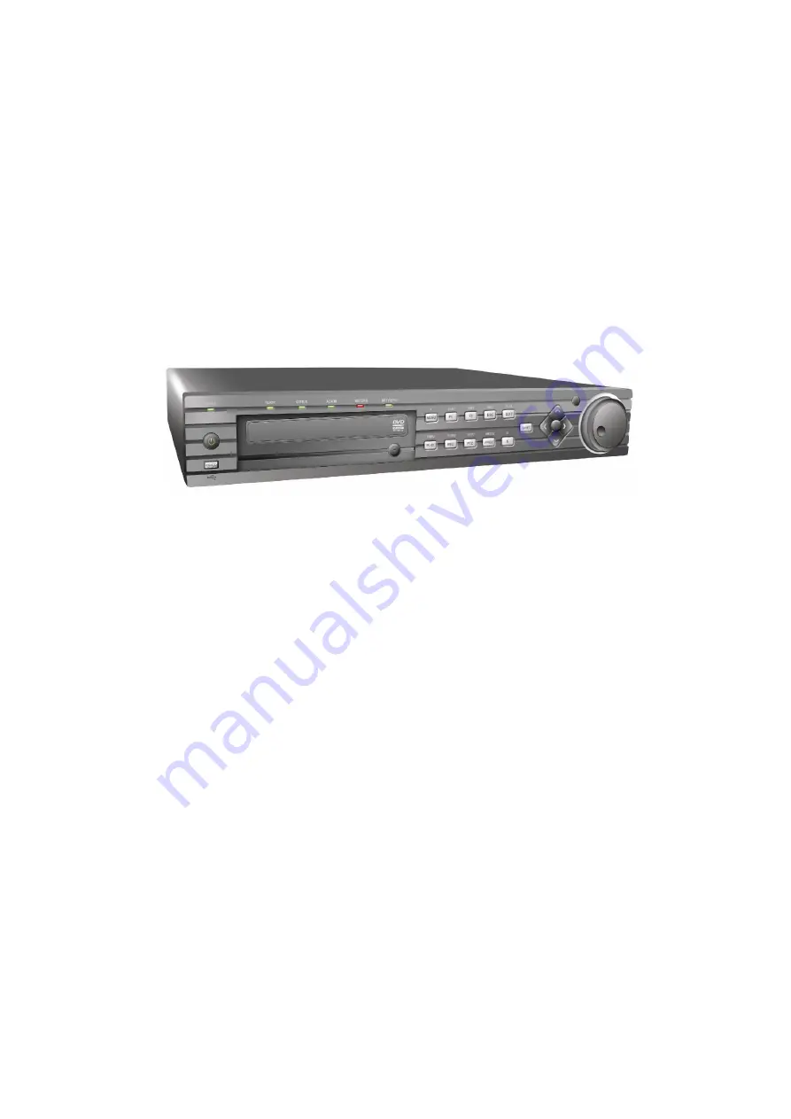
Developed on the basis of the latest technology, the Alien EKO+ range of Digital
Video Recorder combines the latest in advanced H.264 video encoding and decoding
technologies delivering high performance, reliability and longer recording times.  The
Alien EKO+ Digital Video Recorder can be used as a standalone video surveillance
product, as well as the ability to build a powerful surveillance network making it is
perfect for home or business applications.

ALIEN EKO+ DVR

Summary of Contents for ALIEN358

Page 1: ...ALIEN366 Special Features All channels recording at D1 resolution Simultaneous VGA Main Composite Outputs 1FPS background recording switching to 25FPS on motion detection Multi Screen Playback on all channels Networking Email facility Version 2 0 4 Last Revised 18 10 2012 ...

Page 2: ...hich this device will be attached is also connected to properly wired grounded receptacles and are approved devices Power Connect and Disconnect The AC power supply cord is the main disconnect device to mains AC power The socket outlet shall be installed near the equipment and shall be readily accessible Installation and Maintenance Do not connect disconnect any cables or perform installation main...

Page 3: ...to a rack or shelf Major shocks or jolts to the unit as a result of dropping it may cause damage to the sensitive electronics within the unit Use the DVR in conjunction with a UPS if possible Power down the unit before connecting and disconnecting accessories and peripherals A factory recommended HDD should be used for this device Improper use or replacement of the battery could result in battery ...

Page 4: ... 19 2 4 Setting Time Date 22 3 Live Preview 23 3 1 Live Preview On screen Display 23 3 2 Live Preview Icons 23 3 3 Live Preview Operation 23 3 4 Mouse Operation in Live Preview 24 3 5 Digital Zoom 24 3 6 Configure Live Preview Display Channel Zero Encoding 25 3 7 Set Camera Order 26 4 Record Settings 28 4 1 Before Record Settings 28 4 2 Initialising Record Settings 28 4 3 Scheduling a Recording 30...

Page 5: ...u 59 9 2 Configure PTZ Settings 59 9 3 Setting PTZ Presets Patrols Patterns 60 9 4 Customising Presets 61 9 5 Customising Patrols 62 9 6 Customise Patterns 63 10 Camera Management 65 10 1 OSD Settings 65 10 2 Display Settings 65 10 3 Privacy Mask Settings 66 11 HDD Management 68 11 1 Initialising HDDs 68 11 2 Set HDD Groups 68 11 3 Set HDD Status 69 11 4 Setting HDD to Read Only 69 11 5 Checking H...

Page 6: ...pecifications or features without notice Whilst every effort is made to ensure that these instructions are complete and accurate Aliendvr com cannot be held responsible in any way for any losses no matter how they arise from errors or omissions in these instructions or the performance or non performance of the equipment that these instructions refer to This symbol on the products and or accompanyi...

Page 7: ... advanced H 264 video encoding and decoding technologies delivering high performance reliability and longer recording times The Alien EKO Digital Video Recorder can be used as a standalone video surveillance product as well as the ability to build a powerful surveillance network making it is perfect for home or business applications ALIEN EKO DVR ...

Page 8: ...od configurable Digital zoom in live view mode Privacy masking capability Multiple PTZ protocols supported and settings and call up of presets patrols and patterns Video image zoom in by clicking the mouse and dragging mouse in PTZ control mode Hard Disk Management Connection to 1 SATA HDD for with up to 3TB storage capacity DVD writer uses one SATA connection Can replace with additional HDD S M A...

Page 9: ...R remote control Three level user management each user with individual operating permission for DVR and camera Powerful record and search for log of operation alarm and exceptions Import export of device configuration files Network 10 100M adaptive network interface TCP IP network protocols for the UK include SADP DHCP NTP Unicast and multicast supported TCP and UDP protocols applicable in unicast...

Page 10: ... Application Diagram 1 4 Operating Your DVR There are numerous ways to navigate and operate your DVR You may use the Front Panel Controls the included IR Infrared Remote a Mouse or a Soft Keyboard 1 5 Using the Front Panel Controls ALIEN EKO Front Panel ...

Page 11: ...ton is used to cycle through tab pages It will also bring up the Channel OSD position settings 10 4GHI ESC 1 Enter numeral 4 2 Enter letters GHI 3 Exit and back to the previous menu 11 5JKL EDIT 1 Enter numeral 5 2 Enter letters JKL 3 Delete characters before cursor 4 Select the checkbox and ON OFF switch 5 Start stop record clipping in playback 12 IR Receiver Operation by IR remote control 13 JOG...

Page 12: ...ctional buttons In menu mode the direction buttons are used to navigate between different fields and items and select setting parameters In playback mode the Up and Down buttons are used to speed up and slow down record play and the Left and Right buttons are used to select the recording 30s forwards or backwards In preview mode these buttons can be used to cycle through channels Enter The Enter b...

Page 13: ...ARM OUT Connector for 1 alarm outputs 5 POWER Switch for turn on off the device 6 USB Connection for USB device 7 AUDIO OUT RCA connection for 1 analogue audio output 8 VGA DB15 connector for VGA output Display local video output and menu 9 LAN Connector for LAN Local Area Network 10 RS 485 Interface Connector for RS 485 devices T T pin connects to PTZ 11 12V 12VDC power supply connection 12 GND G...

Page 14: ...ARM OUT Connector for 1 alarm outputs 5 POWER Switch for turn on off the device 6 USB Connection for USB device 7 AUDIO OUT RCA connection for 1 analogue audio output 8 VGA DB15 connector for VGA output Display local video output and menu 9 LAN Connector for LAN Local Area Network 10 RS 485 Interface Connector for RS 485 devices T T pin connects to PTZ 11 12V 12VDC power supply connection 12 GND G...

Page 15: ...ame as Alphanumeric buttons on front panel 4 EDIT Same as JKL EDIT button on front panel 5 A Same as 0 A button on front panel 6 REC Same as 7PQRS REC button on front panel 7 PLAY Same as 6MNO PLAY button on front panel 8 INFO Reserved 9 VOIP Same as 2ABC F1 button on front panel 10 MENU Same as 1 MENU button on front panel 11 PREV Same as 9WXYZ PREV button on front panel 12 DIRECTION ENTER Button...

Page 16: ...d there is still no response from the remote please check the following 1 Batteries are installed correctly and the polarities of the batteries are not reversed 2 Batteries are fresh and fully charged 3 IR receiver is not obstructed on DVR 4 No fluorescent lamp is used nearby 1 9 Using a USB Mouse A regular 3 button Left Right Scroll wheel USB mouse can also be used with this DVR To use a USB mous...

Page 17: ...orm task on the DVR clicking on a text input field will bring up the Soft Keypad on screen as shown in Figure 13 Figure 13 Soft Keypad The buttons on the soft keyboard represents Lowercase Designates lowercase input is being used Uppercase Designates uppercase input is being used Switch to Lowercase Switch to lowercase input Switch to Uppercase Switch to uppercase input Number Designates number in...

Page 18: ...ght please apply power to the device to start it After the power has been connected the POWER indicator will light green and the startup window will appear To shutdown the DVR 1 Enter the Shut Down menu shown in Figure 1 by clicking on Menu ShutDown Figure 1 Shutdown Menu 2 Select the ShutDown button 3 Click the Yes button 2 2 Rebooting and Locking Your DVR While in the Shutdown menu Figure 1 you ...

Page 19: ...HDD or click Cancel to access Live View window if no HDD is installed Note If the checkbox is changed to then the Setup Wizard dialog box will not appear next time until the factory default settings are resumed and if you select the checkbox as the device will automatically access the Setup Wizard dialog box when it starts up next time Figure 2 Setup Wizard To start using the Setup Wizard 1 Click ...

Page 20: ...n to enter the HDD Management dialog box shown in Figure 4 Figure 4 HDD Management 6 To access HDD management interface click the Enter button 7 If a new HDD has been recently installed select the HDD from the list to initialise it Initialising the HDD will format and remove all data on it 8 After the HDD has been initialised click the OK button which will take you back to the Setup Wizard window ...

Page 21: ...ctions For EKO Series 11 Select the Schedule tab shown in Figure 6 Figure 6 Schedule Settings 12 Click Edit button to enter a new recording schedule shown in Figure 7 13 Check both the Enable Schedule and All Day checkbox This will enable the recording schedule and make it record continuously all day Figure 7 Edit Schedule Settings ...

Page 22: ...e been entered click Done to finish and exit the Setup Wizard You ve completed the Setup Wizard The next step in the initial setup process is to setup the system date and time After completion of Setup Wizard enter the Live View window 2 4 Setting Date Time It is extremely important to setup the system date and time to accurately timestamp recordings and events 1 Open the Menu window by clicking t...

Page 23: ...ring motion detection or relay alarm Record Indicates the current channel is recording The recording may havebeen started manually from a schedule and or triggered from motion or alarm Event Alarm Record Figure 1 Live Preview Icons 3 3 Live Preview Operation In Live View mode you can operate the following functions 1 Display Single Camera By Front Panel Remote Use Alphanumeric buttons By Mouse Sel...

Page 24: ...displaying less than the maximum number of cameras in Live Preview select this option to switch to the next camera display Playback Enter Playback mode of the selected camera PTZ Enter PTZ Control mode of the selected camera Digital Zoom Enter Digital Zoom interface of the selected camera Menu Enter Main menu Start Auto switch Enable multi camera sequence in Live Preview mode Note The dwell time o...

Page 25: ...n Live Preview Camera Order Set the camera order for display in the selected mode See Setting Camera Order Enable Audio Output Enable disable audio output for the selected video output Event Output Port Set the port for event output to be VGA or Main CVBS Output Event Dwell Time Set the dwell time for event video display Note 1 This DVR will automatically detect whether a VGA monitor is connected ...

Page 26: ...Channel zero encoding Purpose Sometimes you may need to get a remote view of many channels in real time from the web browser or client software using minimal bandwidth requirement without affecting the image quality Channel zero encoding is an option whereby a number of channels can be displayed within the confines of a single channel display without the overhead of a large network bandwidth Enter...

Page 27: ...and the display mode 1 1 2 2 3 3 and 4 4 modes selectable 3 Use the direction buttons on front panel to move to the display pane for setting then press the Enter button to confirm the selection 4 Use the direction buttons on front panel to select the camera you want to view in the display pane The option indicates no camera display 5 Press Enter button to confirm the selection ...

Page 28: ...ttings dialogue box shown in Figure 1 Figure 1 General Record Settings 2 Select the camera you want to configure 3 Configure the following settings Encoding Parameters Set the encoding parameters to be Normal or Event To setup Ramp Up facility refer to section 13 2 Stream Type Set the stream type to be Video or Video Audio Resolution Set recording at resolution of 4CIF 2CIF CIF or QCIF For more in...

Page 29: ...t the actual period for record file storage is determined overall by the available HDD space Record Audio Enable or disable audio record for the selected camera Click OK to finish settings and return to the previous menu 5 Press the 3DEF F2 button on DVR front panel to select the Advanced tab to access the Advanced Settings submenu shown in Figure 3 6 Enable or disable the Overwrite setting Enabli...

Page 30: ...y to enable recording for entire day or select different periods for each day Up to 8 time periods can be scheduled Note The time periods must be in order and must not overlap 8 Select recording Type Recording type can be selected to scheduled or triggered by motion detection and or alarm For more specific settings about motion detection and alarm recordings please refer to Configuring Alarms 9 Cl...

Page 31: ... or OFF for each camera NOTE The manual option overrides any schedule operation 4 5 Protect Recorded Files Two methods are provided to prevent recorded files from being deleted from the HDD or overwritten during cycle recording set the recorded files to be locked or set the HDD that the files reside on to read only 4 6 Lock Unlock Recorded Files To lock or unlock a recorded file 1 Click Menu Video...

Page 32: ...ct the file you want to lock unlock 5 Click the Lock button to lock file If the file is already locked click the Unlock button to unlock file Locked files will be shown with a closed lock while unlocked files opened lock 6 Click Cancel to exit the Video Search menu Figure 7 Video Search Result List 4 7 Set HDD to Read Only To set a HDD to read only 1 Click Menu HDD to access the HDD Management dia...

Page 33: ...hown in Figure 9 Figure 9 HDD Property Settings Menu 5 Set HDD Status to Read only and then click OK to finish the setting Note 1 Once set to read only the HDD cannot be written to until it is set back to read write R W 2 If the DVR is installed with one HDD only when the property is set to read only the recording to the device will stop ...

Page 34: ...lowing figure 16 11 2009Mon11 55 19 Playback Panel Playback Control Panel Figure 1 Playback Interface The Playback Control Panel as shown in Figure 2 provides various control buttons for video playback Audio On Off Start Stop Clip Previous File Day Backward 30s Pause Stop Forward 30s Fast Forwrd Slow Forwrd Next File Day Quit Playback Hide Panel Time Line Record Type Line Figure 2 Playback Control...

Page 35: ... time as shown in Figure 3 Figure 3 Video Search Menu 3 Click the Play button on the front panel to start playback of all the files found or click the Search button to access the list of search results After search results are presented select the file you want to play back and press the Play button 4 Record files will automatically be played back in the Playback interface shown in Figure 4 Figure...

Page 36: ...mode 2 Enter the channel you want to view record video from the front panel or remote control i e press SHIFT the STATUS light will turn green then press 01 for channel 1 press 02 for channel 2 3 Recordings will start for the selected channel Note the record video for playback is of the previous 5 minutes Multi camera Playback 1 Select the cameras from the camera list you want to have simultaneous...

Page 37: ...s will be displayed Select the video log and click Play to play back 4 The selected recording then will begin to play in the Playback interface 5 5 Playback Frame by Frame To play back frame by frame in the Playback interface Using a Mouse 1 Click the Slow Forward button on the Playback Control Panel until the speed changes to Single frame 2 Click the Pause button to advance the video frame by fra...

Page 38: ...38 3 Left click and drag the red box to the desired area for zooming The zoomed image will be magnified by 4 times An example is given in the following figure Figure 7 Digital Zoom in Playback Mode ...

Page 39: ...deo Export to enter the Export Video menu shown in Figure 1 Figure 1 Export Video 2 Select desired parameters to search for files to export 3 On the toolbar press the Export button to enter the Record Backup menu 4 Select the files to export as shown in Figure 2 You may also click the Play button to confirm the record file you want to export Figure 2 Video Search Results ...

Page 40: ...is exported from drop down list USB Flash Drive USB HDD DVD Writer If backup device is not recognised Click the Refresh button Reconnect device Check for compatibility from vendor 6 Click Start to begin backup process shown in Figure 4 Figure 4 Backup Progress 7 After the backup process has completed Figure 5 you may select the files from your device and click the Play button to verify that it has...

Page 41: ... Mouse 1 Enter the Playback interface See Video Playback 2 Click the Clip Start Stop button on the Playback Control Panel and select the start and end of the video clip during playback 3 Repeat for additional clips 4 Click the Quit Playback button to exit from the Playback interface You ll then be prompted to save the clips as shown in Figure 6 Figure 6 Video Clips Saving Prompt 5 Click the Yes bu...

Page 42: ...exit Playback interface 7 At the Backup interface select the Start button to begin the Backup process 6 3 Manage Backup Devices To manage backup devices you must first be in the Export menu shown in Figure 7 The Export menu can be accessed by following the steps shown in the previous section See Exporting Files Figure 7 Export Menus Once in the Export menu you may Create New Folder Creates a new f...

Page 43: ... Camera to access the Camera Settings menu as shown in Figure 1 Figure 1 Camera Management Interface 2 Select the Advanced tab to enter the Advanced Camera Settings menu shown in Figure 2 Figure 2 Advanced Camera Settings 3 Select Motion Detection first and click the Area Settings button to enter the Motion Detection Area and Sensitivity settings interface ...

Page 44: ...ection area Figure 3 Motion Detection Area 5 Right click mouse or press the MENU button on the front panel to set the Motion Detection Sensitivity shown in Figure 4 Higher sensitivity value corresponds to higher sensitivity level Figure 4 Motion Sensitivity Settings 6 Click OK to return to the motion detection area settings interface 7 Right click the mouse to select the Exit from the menu to retu...

Page 45: ...ion detection to be enabled Schedule can be set for all week or any day of the week with up to 8 time periods per day Note After having configured the schedule the DVR must be restarted for the new settings to take effect Figure 6 Schedule Settings 7 Select the Handle tab to configure exceptions handling Exception trigger options will be described in the next section See Understanding Exception Tr...

Page 46: ...e Scheduling a Recording 7 2 Sensor Alarm Settings Recordings can also be triggered from an external relay alarm device To set up sensor alarms 1 Click Menu Settings Alarm to enter the Alarm Settings menu shown in Figure 8 Figure 8 Alarm Management Menu 2 Select the Alarm Input No and click the Set button to enter the Alarm Input Settings menu shown in Figure 9 ...

Page 47: ...b 6 Select cameras to trigger for recording when alarm occurs by checking the checkboxes under the desired cameras as shown in Figure 10 Figure 10 Triggered Cameras Menu 7 User may select the PTZ camera to link with the alarm input and then set the call up of preset patrol and pattern for alarm linked actions 8 Click the OK button to complete setup You may now add a schedule to start recording whe...

Page 48: ...ut Interface 2 Select the output you would like to configure and click the Set button This will bring up the settings page for the selected channel Figure 12 Figure 12 Alarm Output Settings 3 Configure the settings for selected output 4 Select OK to save and exit Note If the Hold For option is selected as Manually Stop the alarm will only stop when you manually stop it See Triggering Alarm Outputs...

Page 49: ... in the Manual Alarm menu Trigger Select an alarm from the list and click Trigger to trigger its output Trigger All Trigger all alarm outputs at once Clear All Stop all alarm outputs at once 3 Select OK to return to the previous menu 7 4 Video Loss Detection Your DVR can be set up to detect video loss and trigger an action To set up video loss detection 1 Click Menu Settings Camera to enter Camera...

Page 50: ...elect the Schedule tab Set the schedule you want video loss detection to be enabled Schedule can be set for all week or any day of the week with up to 8 time periods per day Note After having configured the schedule the DVR must be restarted for the new settings to take effect Figure 16 Schedule Settings for Video Loss Detection 7 Select the Handle tab to configure exceptions handling Exception tr...

Page 51: ...your DVR Note The video tampering detection area is in full screen mode by default and cannot be configured To set up video tempering detection 1 Click Menu Settings Camera to enter the Camera Settings menu shown in Figure 18 Figure 18 Camera Management Menu 2 Select the Advanced tab 3 Select the camera to be configured with video tampering detection 4 Check the Tamper Detection checkbox to enable...

Page 52: ...or all week or any day of the week with up to 8 time periods per day Note After having configured the schedule the DVR must be restarted for the new settings to take effect Figure 20 Schedule Settings for Video Tampering Detection 7 Select the Handle tab to configure exceptions handling Exception trigger options will be described in the next section See Understanding Exception Trigger Options Figu...

Page 53: ... Video Output Standard Mismatch video output standards do not match with each other To set exceptions 1 Click Menu Settings Exception to enter the Exception menu 2 Select the exception to configure under Exception Type 3 Select triggering options as shown in Figure22 Trigger options are further explained in the next section See Understanding Exception Trigger Options Figure 20 Exception Menu 4 Cli...

Page 54: ...ifferent dwell time can be set by going to Menu Setting Display Dwell Time Once the alarm stops cycling of the images will also stop and you ll be returned to the Live Preview screen Audio Warning Trigger an audible beep when exception is detected Notify Surveillance Centre Sends a signal to remote alarm host when exception is detected See Configure Remote Alarm Host Trigger Alarm Output Trigger a...

Page 55: ...he Network Settings menu shown in Figure 1 Figure 1 Network Settings Menu 2 Select the General tab Configure the settings on the interface 3 If you have a DHCP server running and would like your DVR to automatically obtain an IP address and other network settings from that server check the DHCP checkbox You may check the DHCP status by going to the Network Status tab as shown in Figure 2 Figure 2 ...

Page 56: ...TP Server may also be set up on your DVR to maintain accurate current date and time To set up an NTP server 1 Click Menu Settings Network to enter the Network Settings menu 2 Select the Advanced tab 3 Click the Set button next to NTP to enter the NTP Settings menu as shown in Figure 8 Figure 8 NTP Settings Menu 4 Check the NTP checkbox to enable this feature 5 Configure NTP settings Synchronize In...

Page 57: ...ill send a signal to the host when an alarm is triggered The remote alarm host must use a bespoke software product and this is not available in CCTVWindow 1 Enter Network settings menu by clicking Menu Setting Network 2 Select the Advanced tab 3 Click the Set butt next to Host Others to enter the Host Others menu as shown in Figure 9 Figure 9 Host Others Menu 4 Enter Alarm Host IP and Alarm Host P...

Page 58: ...he default ports 1 Click Menu Settings Network to enter the Network Settings menu 2 Select the Advanced tab 3 Click the Set button next to Host Others to enter the Host Others menu 4 Enter new Server Port and HTTP Port as shown in Figure 11 Figure 11 Host Others Menu Note The Server Port has a port range of 2000 65535 and is used for remote client software access The HTTP port is used for remote I...

Page 59: ...equence Call Pattern Call a PTZ pattern Preset Settings Enter PTZ preset configuration menu Patrol Settings Enter PTZ sequence configuration menu Pattern Settings Enter PTZ pattern configuration menu PTZ Menu Enter PTZ control menu PTZ Settings Enter PTZ settings menu 9 2 Configure PTZ Settings Settings for a PTZ camera must be configured before it is used Before proceeding verify that the PTZ and...

Page 60: ... The settings asterisked normally are the defaults for most PTZ cameras 4 Click OK to save settings and exit the PTZ Settings menu Note All setting parameters baud rate data bit stop bit parity flow control PTZ protocol and address must be consistent with the PTZ camera connected 9 3Setting PTZ Presets Patrols Patterns The DVR allows you to program presets patrols and patterns for a range of PTZ c...

Page 61: ...location To set up and call custom PTZ presets 1 Enter the PTZ Control interface shown in Figure 3 by selecting PTZ from the mouse menu or clicking the PTZ button on the front panel 2 Select the Preset button to enter the Preset Management menu 3 In the Preset Management menu shown in Figure 4 you may Configure Preset Use the PTZ control panel to adjust the position of the preset Select a Preset n...

Page 62: ... to enter the Patrol Management menu shown in Figure 5 Figure 5 Patrol Management Menu 3 In the Patrol Management menu you may Configure a Patrol 1 Select a Patrol Number to set 2 Select valid presets See Customise Presets and click the Set button to enter the Patrol configuration menu A sequence should have at least 2 valid presets 3 Set the Key Point No Duration and Speed Figure 6 The Key Point ...

Page 63: ...elete patrol Call Patrol 1 Select a valid Patrol Number 2 Click the Start button to call the patrol and select the Stop button to stop the patrol as shown in Figure 7 Figure 7 Patrol Management Menu 9 6 Customise Patterns Patterns can be setup by recording the movement of the PTZ To set up and call PTZ patterns 1 Enter the PTZ Control interface shown in Figure 3 by selecting PTZ from the mouse men...

Page 64: ...s of the PTZ Use the PTZ control panel to move the PTZ The PTZ movements will be recorded until the Stop Record button is clicked 5 To run a pattern click the Run Pattern button on a valid pattern The PTZ will move according to the path that was defined until Stop Pattern is clicked 6 Click OK to exit the current menu ...

Page 65: ...the OSD display position including the camera name position and the date time display position 10 2 Display Settings Display settings such as the brightness contrast saturation and hue can also be adjusted in the Camera Management menu To adjust display settings 1 Click Menu Settings Camera to enter the Camera Settings menu shown in Figure 1 2 Click the Advanced tab to enter the Advanced Camera Se...

Page 66: ...ettings Camera to enter the Camera Settings menu 2 Click the Advanced tab to enter the Advanced Camera Settings menu as shown in Figure 1 Select channel for privacy mask settings in Camera Figure 1 Advanced Camera Settings Menu 3 Check the Mask checkbox to enable feature 4 Click the Area Settings button to enter Area Settings menu 5 Set mask area as shown in Figure2 Up to 4 areas can be set ...

Page 67: ...67 Figure2 Setting Mask Area 6 Select Exit to save settings and exit the Mask Area Settings interface ...

Page 68: ...nitialised 3 Click the Init button 4 Select OK button to start initialisation After the HDD has been initialised the status of the HDD will change from Abnormal to Normal 11 2 Set HDD Groups Your DVR can separate multiple HDDs into groups Videos from specified channels can be set to be recorded onto a particular HDD group To set up an HDD group 1 Click Menu HDD to enter the HDD Management menu 2 S...

Page 69: ... status of a HDD can be set to read only or read write R W 11 4 Setting HDD to Read Only A HDD can be set to read only to avoid important recorded files from being overwritten when the HDD becomes full To set a HDD to read only 1 Click Menu HDD to enter the HDD Management menu 2 Select HDD to be protected 3 Select the Property button to enter the Property Settings menu as shown in Figure 3 Figure ...

Page 70: ...he status is listed as Normal or Hibernate the HDD is in working order If it is listed as Abnormal and has already been initialised the HDD needs to be replaced If the HDD is Uninitialised you will need to initialise it before it can be use in your DVR Please refer to Initialising HDDs for further instructions You may also view the SMART information of installed HDDs SMART which is an abbreviation...

Page 71: ... Log Search Results 1 Select log item to view and click the Details button A detail list of SMART information as shown in Figure 6 will be displayed Figure 6 HDD SMART Information User can also click Menu HDD to enter the HDD management menu as shown in Figure 1 and then select the Advance option to enter the SMART menu as shown in Figure 7 User can enable the SMART function and view the SMART inf...

Page 72: ...s uninitialised or in an abnormal state To set HDD alarms 1 Click Menu Settings Exception to enter Exception menu shown in Figure 8 Figure 8 Exception Menu 2 Select HDD Error under Exception Type 3 Select trigger action Trigger actions are further explained in Understanding Exception Trigger Options ...

Page 73: ...ings including Language Default language used in DVR menus CVBS Output Standard Video output standard NTSC and PAL VGA Resolution VGA output resolution Time Zone Time zone to use for DVR Menu Date Format Format for date System Time System time and date Mouse Pointer Speed Speed of mouse pointer Enable Password Enable disable system password Note If the video standard is different between the input...

Page 74: ...lowing settings Device Name Name of the DVR used Device No Device number of DVR CVBS Output Brightness Video output brightness Transparency Menu transparency Operation Timeout Set timeout time for menu inactivity For example if timeout time was set to 5 minutes after 5 minutes of inactivity in the General Settings menu you ll be returned to the Live Preview Output Hint Enable disable video output ...

Page 75: ...gure 5 Add User Menu Enter information for new user including User Name Password Level and User s MAC 2 The Level is the user level and is separated into two tiers Operator By default the Operator user level has the authority to configure two way audio in network settings and all parameters in channel settings Guest By default the Guest user cannot configure network settings but can configure the ...

Page 76: ...configure network permission settings as shown in Figure 7 The network settings include Figure 7 Network Permission Settings Menu Remote Log Search Remotely view logs that are saved on the DVR Remote Configuration Remotely configure parameters restore parameters to factory defaults and import settings to as well as export settings from DVR Remote Serial Port Control Configure settings for RS232 an...

Page 77: ...t and view live video over the network Local Manual Record Locally start and stop manual recording on any of the channels Remote Record Starting Remotely start and stop manual recording on any of the channels Local Playback Locally play recorded files that are on the DVR Remote Playback Remotely play and download recorded files that are on the DVR Local PTZ Control Locally control PTZ cameras Remo...

Page 78: ...d for the Administrator 12 4 3 Modifying a User To modify a user 1 Click Menu Settings User to enter the User Settings menu 2 Select user to modify 3 Click the Modify button to enter the Modify menu shown in Figure 9 Figure 9 Modify User Menu 4 Edit user information 5 To modify user permissions click on the privileges button Permissions settings are defined in the Adding a New User section describ...

Page 79: ...int to the DVR 3 To import a configuration file select the file from the USB device and click the Import button After the import process is completed the system will automatically reboot the DVR 4 Click Cancel to exit the current menu 12 6 Updating System Firmware The firmware on your DVR can be updated by using two methods These methods include updating via an USB device or over the network via a...

Page 80: ... the system firmware has been updated reboot the DVR To update via a FTP server Only for engineer workshop users only as needs third party TFTP software Note Do not attempt to change your DVR s firmware unless instructed to do by your supplier Upgrade failure may render your DVR useless and necessitate it s return to the manufacturer distributor for repair ...

Page 81: ...shown in Figure 13 Figure 13 Default Settings Menu 2 Select OK to restore factory defaults Note Network information such as IP address subnet mask and gateway will not be restored 12 8 View System Information To view system information 1 Click Menu Maintenance Information to enter the Information menu shown in Figure 14 Figure 14 System Information ...

Page 82: ...h button to start search If logs matching the search conditions are found it will be displayed in a list of search results as shown in Figure 16 Figure 16 Log Search Results 4 To view more detailed information about a particular log entry select the log and click the Details button 5 If applicable you may also view the associated video to the selected log entry by clicking the Play button 6 Log fi...

Page 83: ...rt menu shown below in Figure 17 Click the Export button to export log onto USB device The exported file will be named according to the time it was exported e g 20100911143958logBack txt Figure 17 Log Search Export Menu 8 Click Cancel to exit the current menu ...

Page 84: ...r a networked device such as a router or computer system using the Internet Protocol Suite to notify a domain name server to change in real time ad hoc the active DNS configuration of its configured hostnames addresses or other information stored in DNS Hybrid DVR A hybrid DVR is a combination of a DVR and NVR NTP Acronym for Network Time Protocol A protocol designed to synchronise the clocks of c...

Page 85: ...ected to revert to 25fps recording 1 Enter System Settings 2 Select camera number required 3 Ensure Encoding Parameters set to Normal 4 Reduce frame rate to low rate 5 Select OK and re enter Record Settings 6 Click the Encoding Parameter again for same channel but click on down arrow and select Event 7 Select higher Frame Rate example 25 fps 8 Select OK 9 Select Camera Settings ...

Page 86: ...the Handle option you can tick the Pop up image on Monitor to display a single screen display of the triggered camera 15 Click on OK and confirm in each menu to save 16 Repeat for other camera channels 17 To check that settings are correct the red record light must be on permanently and when motion occurs the yellow icon for event will display ...

Page 87: ...15hr 3dy 7hr 3dy 20hr 5dy 3hr 7dy 17hr 10dy 7hr 12 3dys 7hr 6dy 14hr 7dy 17hr 10dy 7hr 15dy 11hr 20dy 14hr 6 6dy 14hr 13dy 4hr 15dy 11hr 20dy 14hr 30dy 22hr 41dy 5hr 4 8dy 19hr 17dy 14hr 20dy 14hr 27dy 11hr 41dy 5hr 54dy 23hr 2 17dy 14hr 35dy 4hr 41dy 5hr 54dy 23hr 82dy 10hr 109dy 22hr 1 35dy 4hr 70dy 8hr 82dy 10hr 109dy 22hr 164dy 21hr 219dy 20hr 4CIF mode Maximum 25FPS Frame Rate HDD 320Gb HDD 6...

Page 88: ...y 14hr 7dy 17hr 10dy 7hr 15dy 11hr 20dy 14hr 12 6dy 14hr 13dy 4hr 15dy 11hr 20dy 14hr 30dy 22hr 41dy 5hr 6 13dy 4hr 26dy 9hr 30dy 22hr 41dy 5hr 61dy 20hr 82dy 10hr 4 17dy 14hr 35dy 4hr 41dy 5hr 54dy 23hr 82dy 10hr 109dy 22hr 2 35dy 4hr 70dy 8hr 82dy 10hr 109dy 22hr 164dy 21hr 219dy 20hr 1 70dy 8hr 140dy 17hr 164dy 21hr 219dy 20hr 329dy 18hr 439dy 17hr 4CIF mode Maximum 25FPS Frame Rate HDD 320Gb H...

Page 89: ...5FPS 25FPS MAINSTREAM 4CIF 25FPS 25FPS SUBSTREAM CIF 6FPS 6FPS SUBSTREAM QCIF 25FPS 25FPS SUBSTREAM MAX FRAMES 25FPS 25FPS TOTAL TCP CONNECTIONS 24 24 TOTAL TCP CONNECTIONS PER CHANNEL 3 3 TOTAL TCP CONNECTIONS This is the total TCP connections per DVR TOTAL TCP CONNECTIONS PER CHANNEL This is the total TCP connections to a single DVR channel ...

Page 90: ...ound and make sure there are no fluorescent lamps in use Why does the PTZ seem unresponsive If the PTZ seem unresponsive please check 1 Check that the RS 485 cable is correctly polarity connected 2 Check that the dome protocol is correct 3 Check that the dome baud rate is correct 4 Check that the dome ID is correct 5 Check to make sure that the main board RS 485 interface is not faulty Why is ther...

Page 91: ...user defined Stream type Video Video Audio Audio bit rate 64kbps Dual stream Support Playback 8 ch Video Audio input Voice talk input 1 ch RCA 2 0Vp p 1k Hard disk Type 1 x SATA interface Max 3Tb DVD Writer Type 1 x SATA interface If not needed can be used for HDD Network interface 1 x RJ45 10M 100M adaptive Ethernet interface Serial interface 1 RS 485 interface 1 RS 232 interface USB interface 2 ...

Page 92: ...kbps user defined Stream type Video Video Audio Audio bit rate 64kbps Dual stream Support Playback 16 ch Video Audio output Voice talk input 1 ch RCA 2 0Vp p 1k Hard disk Type 1 x SATA interface Max 3Tb DVR Writer Type 1 x SATA writer interface If not needed can be used for HDD Network interface 1 x RJ45 10M 100M adaptive Ethernet interface Serial interface 1 RS 485 interface USB interface 2 x USB...

Reviews: