


6
www.observint.com
© 2018 Observint Technologies. All rights reserved.
maintenance cable to the connector on the maintenance panel, and then attach it to CVBS monitor to see a
live view video from the camera.
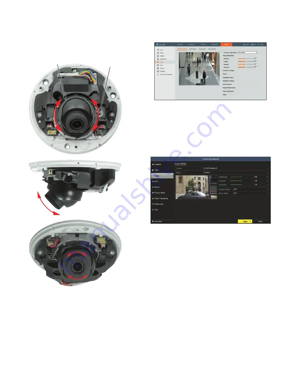
1. While observing live video from the camera, use a #2 Phillips screwdriver to loosen the gimbal lock
screw until the gimbal is free to rotate (about three turns). The location of the lock screw is shown in
the photos on page 1 of this guide.
2. Point the camera at your surveillance target, changing the pan, tilt and rotation as needed. See below.
Always stay within the specified pan, tilt and rotation ranges of the camera.
Gimbal lock screw
Gimbal assembly
Pan range:
-30° ~ +30°
Tilt range:
0˚ ~ 75˚
Rotation range:
0˚ ~ 360˚
3. Tighten the adjustment lock screw to securely hold the gimbal in place.
4. Reinstall the camera dome cover.
5. Reinstall the camera outer cover.
Step 8. Adjust the camera image for your surveillance target
Use the firmware menus to adjust the brightness, contrast, saturation and sharpness of the video image
if necessary. These settings are initially optimized at the factory and may not need adjustment. When
adjustments are necessary, the paths to the image settings menus are different if the camera is installed
as a device on a LAN, or if it is connected to a NVR. Select the installation type below for your camera to
complete this step.
For cameras installed on a LAN
1. If necessary, open IE and log into the camera with administrative credentials.
2. Click the
Setup
tab, and then click the
Image
link in the left frame.
3. Adjust the Brightness Contrast, Saturation and Sharpness of the image. Each parameter can be set to a
level of 0 ~ 100 either by moving the slider or entering the value in the box on the right. The effect of
the adjustment will appear in the Live View image in the menu.
Refer to the firmware user manual for your camera to use the other submenus on this screen.
For cameras connected directly to an NVR
1. Log into the NVR with administrative privileges.
2. Open the firmware Image menu. Go to
Menu | Camera Management | Image
3. In the
Camera
field drop down list, select the camera you want to configure. In the example above,
[D1]IPCamera 01
is selected.
4. Drag the
Brightness
,
Contrast
,
Saturation
and
Hue
adjustment markers left or right to perfect
the image from the camera. For some adjustments, you can click the up (
5
)or down (
6
)icons
near the adjustment value (on the right side) to incrementally change the value of those adjustment.
5. Click
Apply
to save your settings for this camera.
Refer to the firmware user manual for your NVR to use the other submenus on this screen.
Cleaning
Dust or grease on the dome cover will cause IR reflection. Please do not remove the dome cover film until
the installation is finished. If there is dust or grease on the dome cover, clean the dome cover with clean soft
cloth and isopropyl alcohol.
Do not touch lens with fingers. If cleaning is necessary, use clean cloth with ethanol and wipe it gently. If
the camera will not be used for an extended period, please replace the lens cap to protect the sensor from
dirt.


