


3
www.observint.com
© 2014 Observint Technologies. All rights reserved.
6.
Connect the extension cables to the camera drop cables. Use the protective jacket for the LAN cable
connector, if needed.
NOTE
Drop cable connectors are not waterproof.
7.
Position the camera at the mounting location so that the screws heads are in the mounting screw
slots, and then turn the camera clockwise until the screws are fully seated in the slots.
8.
Tighten the mounting screws until snug. Be careful not to over-tighten them.
9.
Connect the extension cables to the devices the camera will connect to. Be sure the devices you
connect the cables to are not powered on.
10. Apply power to the devices the camera is connected to, including 12 Vdc power or LAN PoE.
11. Reinstall the camera bezel.
12. Remove the protective film from the camera lens dome. Clean the dome with isopropyl alcohol if
needed.
13. Using a computer connected to the LAN the camera is attached to, configure the network access to
the camera including:
—
Install Alibi Discover (see “Step 4. Install the Alibi Discover Tool” on page 3).
—
Configure the network settings (see “Step 5. Change device network settings (IP address)”
on page 3).
14. Log into camera to perform camera setup procedures including:
—
Log in to the camera (see “Step 6. Initial remote login” on page 4).
—
Configure camera fisheye parameters (see “Step 7. Setup Fisheye Parameters” on page 5).
For ceiling mounted cameras, select the
Mount Type
as “
Ceiling
”. For wall mounted
cameras, select the
Mount Type
as “
Wall
”. For table mounted cameras, select the
Mount
Type
as “
Table
”.
—
Configure PTZ camera video streams (see”Step 9. Setup PTZ video streams” on page 5).
—
Change administrative password. See “Step 10. Change default password” on page 6.
15. Perform advanced camera configuration steps as needed. Refer to the
ALIBI™ IP Camera
Software User Manual
provided on CD with your system, or on your vendor’s website. These
configure steps should include the following:
—
Configuring alarm input and output
—
Configure recording schedules
—
Configure event recording (motion detection, traversing virtual plane, intrusion, etc.)
—
Traversing Virtual Plane Detection
—
Intrusion Detection
—
Add access users to the camera
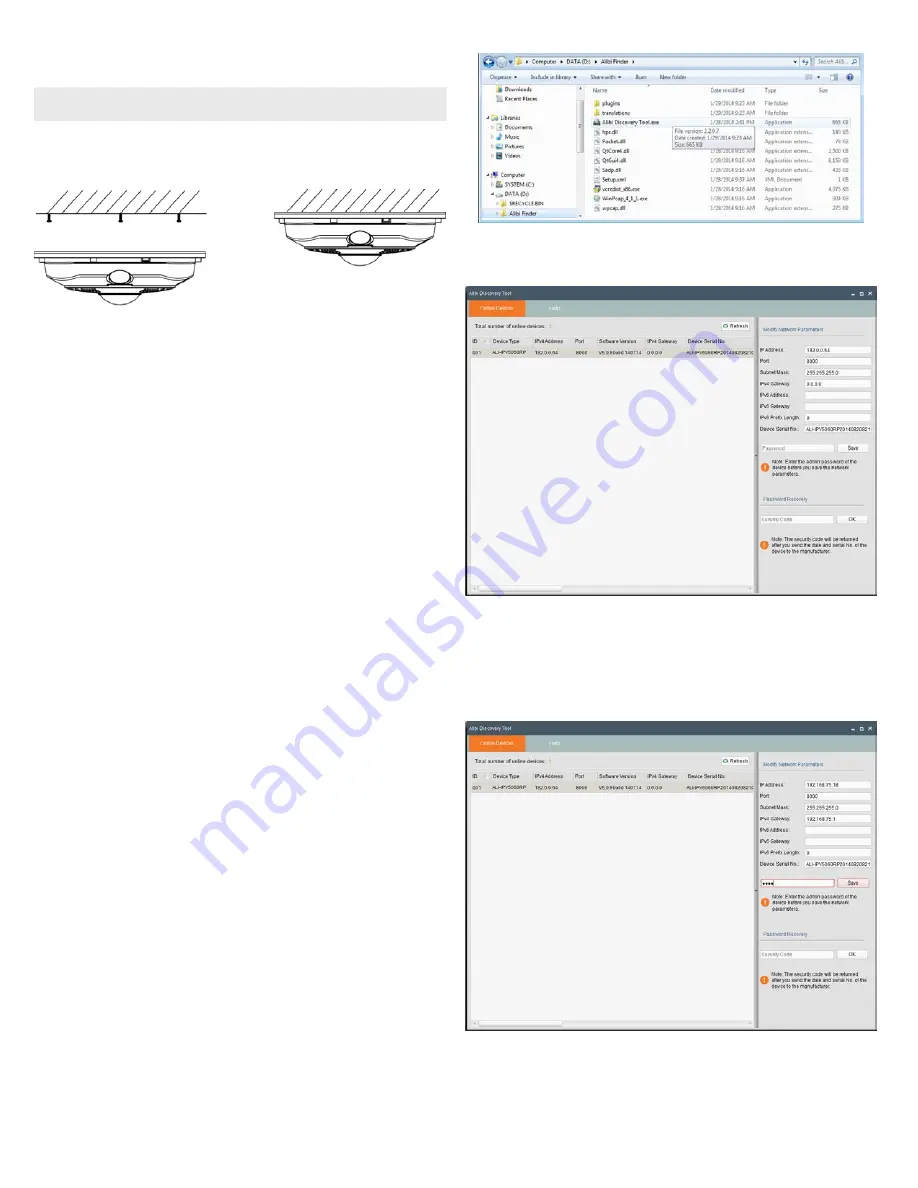
Step 4. Install the Alibi Discover Tool
The ALIBI Discover Tool is a software utility used to “discover” ALIBI cameras and NVRs/DVRs installed on
the LAN and change their network settings. The tool is provided on the CD with your camera. To use the
tool:
1.
Insert the software CD provided with your camera into an optical drive on the Microsoft Windows
computer you will use to access your camera on the LAN.
2.
On the CD, find the folder that contains the ALIBI Discover Tool.
3.
Copy the files in the folder to a new directory on your computer. The files should appear as shown in
the directory shown below.
4.
To open the ALIBI Discover Tool, double click the file
ALIBI Discover Tool.exe
. The tool will
automatically discover ALIBI cameras and recorders installed on the network.
Step 5. Change device network settings (IP address)
To change the network settings of the camera to be compatible with the subnet where it is installed, do the
following:
1.
Click the device to highlight it. Notice that the network parameters are shown in the right frame.
2.
Modify the network settings to values compatible with the subnet where it is installed.
3.
Enter the
admin
password for the device in the password field. By default, the
admin
user
password for ALIBI cameras is
1111
.
4.
Click the
Save
button. A parameter modification completion window will open.


