


9
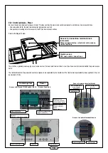
Wiring diagram - junction box:
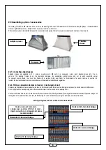
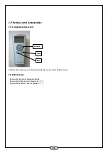
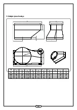
2.6.3 Connecting standard or insulated flexible sleeves
Flexible sleeves are available in the standard version (one layer of glass fibre, fire resistance rating M0) or insulated version (two layers of glass fibre,
insulated with a 5 mm glass wool felt), supplied with 4 M8 screws, 8 washers and 4 nuts. The sleeve may be fixed to a damper or directly to the opening
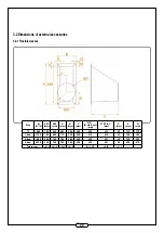
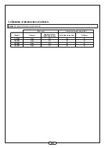
frames. For sleeve dimensions, refer to section 3.2.1.
Screw each flexible sleeve into the inserts of the opening frame or on to the insulation dampers, by fitting the washer, screw and nut in each assembly
corner. Insulate the ducts in accordance with applicable standards and regulations.
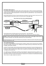
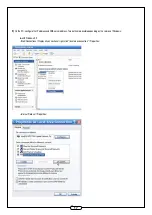
2.6.4 Connecting the CO
2
sensor
The CO2 sensor is supplied as an accessory. It must be connected to the terminal
block according to the diagram below (24 V AC / GND and 1-10V input).
3-way connector
3-way connector
Damper servo-motor cable
RG cable
To damper
To terminal block
3-way connector
3-way connector
Damper servo-motor cable
Damper servo-motor cable
RG cable
To damper
To terminal block
Black
Red
CO2 sensor
1
2
3
4
5
6
+V GND RH
T CO2 GND
24V AC GND
0-10V GND
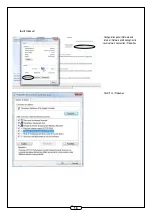
Control terminal connection
Labels
Definition
Comments
M17
Air supply temperature sensor
Sensor connected in factory
M16
M12
CO2 sensor – 010 V
Active if option selected
M4
GND
Bridged by default on terminal block
M5
CTA external shutdown
M4
GND
NO
M3
High speed
M8
Fire Alarm contact
Bridged by default on terminal block
M7
GND
M34
CTA Alarms (A) return relay
NO
M35
M36
CTA Alarms (B) return relay
NO
M37
RG1
Fresh air damper relay -
ON/OFF
NO (Active if option selected)
RG2
+24
24V AC
Damper servo-motors
-24
+24
24V AC
CO2 probe
-24
Single damper
New air or exhaust air
2 dampers in parallel
New air or exhaust air
Junction box
Junction box


