

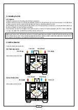
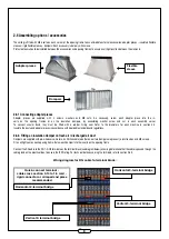


10
2.6.5 Optional internal water coil
The internal water coils are supplied with two flat seals, a motor-driven and pre-wired 3-way valve, a BW control wire and a frost-protection tempera-
ture sensor (to measure the temperature of the fluid circulating in the coil). The flat seals and the 3-way valve are for the time being left in the optional
accessories box. The BW wire and the frost-protection sensor are connected at one end to the control terminal block. They are left unattached at the
other end, ready to be installed.
Make the hydraulic connection for the water coil, where the inlet and outlet are on the side wall. Connect the 3-way valve to the coil water circuit. Once
the hydraulic connections are made, connect the wires for the internal water coil (refer to wiring diagram below).
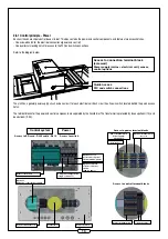
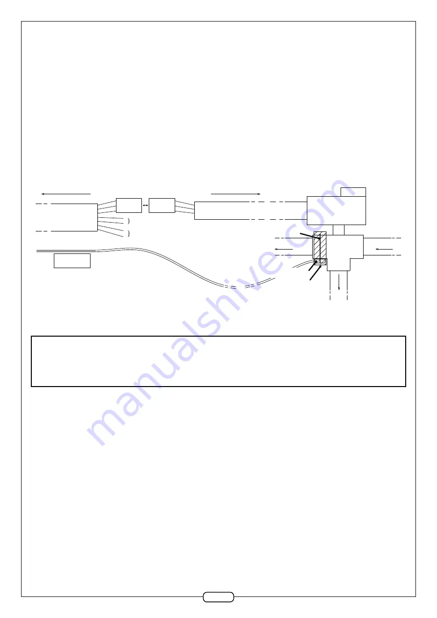
Servo-motor and 3-way valve assembly diagram:
1
2
3
4
5
6
7
To Unit connection terminal block
BW cable
Temperature
sensor
on 3-way valve
Heat pump - ON/OFF
Male
3-point
connector
Female
3-point
connector
Servo-motor cable 3-way valve
To 3-way valve
Clip collar
Coil water circuit
Temperature
sensor
Insulation
3-way valve
Servo-motor
Coil water circuit
Cooling pump - ON/OFF
Attach the BW male connector to the female connector on the servo-motor (strands 1, 2, and 3 of the BW cable).
If so desired, attach the 4 free strands of the BW cable used to control the stop or start functions of the hot or cold water coil circuit pump.
Caution:
the electrical connections of external devices or which are located in a humid environment must be watertight. We recommend that you
protect the connections between the servo-motor cable and the BW cable, using at least an IPX5 protection.
Attach the temperature sensor to the 3-way valve of the internal coil using a plastic collar. To increase the precision of fluid temperature measurement,
insulate the sensor and the 3-way valve.
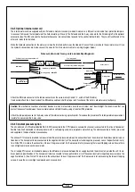
2.6.6 Constant pressure option
The kit contains 3 x RJ12 cables (labelled R8, R9, R10) connected to the 2 PTH pressure sensors. Each sensor is connected to 2 metres of transparent
flexible tube, itself connected to a black pressure inlet. 4 self-tapping screws are supplied in a plastic bag. The whole assembly is factory pre-wired
and supplied in the box of optional accessories.
The exhaust PTH sensor is intended to measure the difference in pressure between the exhaust duct and the ambient air. Its address pointer is posi-
tioned on 6. The transparent tube is connected to the negative terminal (-) of the sensor (duct under negative pressure). Leave the positive terminal (+)
free. Drill a Ø10 mm hole in the exhaust duct to insert the pressure inlet. Fix the pressure inlet in place using the two self-tapping screws. Ensure there
is an airtight seal around each pressure inlet.
The air supply PTH sensor is intended to measure the difference in pressure between the air supply duct and the ambient air, outside the unit. Its ad-
dress pointer is positioned on 5. The transparent tube is connected to the negative terminal (-) of the sensor (duct under negative pressure). Leave the
negative terminal (-) free. Drill a Ø10 mm hole in the exhaust duct to insert the pressure inlet. Fix the pressure inlet in place using the two self-tapping
screws. Ensure there is an airtight seal around each pressure inlet.


