background image


30 

ATS9360 User Manual


Calibration 

Calibration


is the process of minimizing measurement errors 

by making small circuit adjustments.   
 
All ATS9360 digitizers come factory calibrated to the levels 
indicated in Appendix A, Specifications. Note that AlazarTech 
calibration is fully NIST traceable. 
 
However, your digitizer needs to be periodically recalibrated 
in order to maintain its specified accuracy. This calibration 
due date is listed on the CALIBRATION sticker affixed to your 
ATS9360 digitizer. 
 
Externally recalibrate the ATS9360 when this calibration 
interval has expired.  
 
This requires three very simple steps: 
 

1.  Verify whether or not ATS9360 is still within its 

specifications.  If it is, then your calibration can be 
extended by another one-year period 

2.  If not, perform calibration, i.e. make adjustments to 

the circuit until it is within specifications again 

3.  If any adjustments have been made, verify if the 

ATS9360 is within specifications 

 
Recalibration must be performed at AlazarTech factory. 


Summary of Contents for ATS9360

Page 1: ...ATS9360 User Manual 12 Bit 1 8 GS s Waveform Digitizer for PCI Express Gen2 Bus Written for Hardware Version 1 2 April 2013 Edition Part Number 9360 USR 1 ...

Page 2: ......

Page 3: ...ent on the documentation for ATS9360 send e mail to support alazartech com Information required when contacting AlazarTech for technical support Owned by ___________________________ Serial Number ___________________________ Purchase Date ___________________________ Purchased From ___________________________ Software Driver Version ___________________________ SDK Version ___________________________...

Page 4: ...c be liable for any damages arising out of or related to this document or the information contained in it The latest user manual can be found on the AlazarTech Inc web page at www alazartech com support downloads htm EXCEPT AS SPECIFIED HEREIN ALAZARTECH INC MAKES NO WARRANTIES EXPRESS OR IMPLIED AND SPECIFICALLY DISCLAIMS ANY WARRANTY OF MERCHANTABILITY OR FITNESS FOR A PARTICULAR PURPOSE CUSTOME...

Page 5: ... OR ERRORS ON THE PART OF THE USER OR APPLICATIONS DESIGNER ADVERSE FACTORS SUCH AS THESE ARE HEREAFTER COLLECTIVELY TERMED SYSTEM FAILURES ANY APPLICATION WHERE A SYSTEM FAILURE WOULD CREATE A RISK OF HARM TO PROPERTY OR PERSONS INCLUDING THE RISK OF BODILY INJURY AND DEATH SHOULD NOT BE RELIANT SOLELY UPON ONE FORM OF ELECTRONIC SYSTEM DUE TO THE RISK OF SYSTEM FAILURE TO AVOID DAMAGE INJURY OR ...

Page 6: ...liance mark Consult the FCC web site http www fcc gov for more information FCC DOC Warnings This equipment generates and uses radio frequency energy and if not installed and used in strict accordance with the instructions in this manual and the CE Mark Declaration of Conformity may cause interference to radio and television reception Classification requirements are the same for the Federal Communi...

Page 7: ...ocuments htm This web page lists all DoCs by product family Select the appropriate product to download or read the DoC Certain exemptions may apply in the USA see FCC Rules 15 103 Exempted devices and 15 105 c Also available in sections of CFR 47 The CE Mark Declaration of Conformity will contain important supplementary information and instructions for the user or installer Environmental Complianc...

Page 8: ...rted 10 Unpacking 11 Installing the ATS9360 12 Installing the ATS9360 in a Linux System 20 Compiling the ATS9360 Linux Driver 21 Updating ATS9360 Driver 22 CHAPTER 3 HARDWARE OVERVIEW 24 Input Connectors 26 Signal Connections 27 Analog Input 28 Amplifier Bypass Option Error Bookmark not defined Calibration 30 Master Slave Operation Error Bookmark not defined Optional External Clock 31 Streaming Us...

Page 9: ...ATS9360 User Manual 1 Chapter 1 Introduction This chapter describes the ATS9360 and lists additional equipment ...

Page 10: ...ge Streaming of acquired data to PC host memory at 3 5 GB s exact rate is motherboard dependent 800 MHz analog input bandwidth Half length PCI Express 8 lane card External trigger input channel with software selectable level and slope DC coupling and fixed 50 input impedance for analog inputs Pre trigger and Post Trigger Capture with Multiple Record capability NIST traceable calibration Dual DMA e...

Page 11: ...9360 digitizers follow industry standard Plug and Play specifications on all platforms and offer seamless integration with compliant systems Detailed specifications of the ATS9360 digitizers are listed in Appendix A Specifications ...

Page 12: ...d a reference manual describing the API For programming in LabVIEW you must purchase the ATS VI virtual instrument library that comes with a high level easy to use VI that makes integrating the ATS9360 into your own system very simple AlazarTech offers ATS9360 binary drivers for CentOS 6 3 x86_64 with kernel 2 6 32 279 5 2 el6 x86_64 These drivers are also 100 compatible with RHEL 6 3 Source code ...

Page 13: ...60 as you would a desktop oscilloscope To launch the AlazarDSO select Start Programs AlazarTech AlazarDSO The following screen will be displayed If you connect the input to a signal generator and click on Start button you should see the signal on the screen AlazarDSO has been designed to be very intuitive and uses a user interface similar to most of today s digital oscilloscopes ...

Page 14: ... The ATS SDK sold separately API is used for programming the ATS9360 in C C and MATLAB It provides the exact same API that is used for writing AlazarDSO software To help you get started ATS SDK comes with examples you can use or modify ...

Page 15: ...9360 sold separately can be used for programming the ATS9360 under Linux operating system A source code driver is supplied that has been compiled for CentOS 6 3 x86_64 with kernel 2 6 32 279 5 2 el6 x86_64 running on an i386 platform Sample programs are supplied in C The API is identical to the Windows API Note that you will need to sign a Non Disclosure Agreement with AlazarTech in order for the ...

Page 16: ...rs the following upgrades and accessories for use with your ATS9360 digitizer ATS9360 Standard External Clock Upgrade 300MHz to 1 8 GHz ATS9360 Screened External Clock Upgrade 75MHz to 1 8GHz AlazarDSO Stream To Disk Module AlazarDSO Plug In Development Kit ...

Page 17: ...ATS9360 User Manual 9 Chapter 2 Installation and Configuration This chapter describes how to unpack install and configure your ATS9360 ...

Page 18: ...10 ATS9360 User Manual What You Need to Get Started To set up and use your ATS9360 you will need the following One or more ATS9360 digitizers ATS9360 Installation Software on USB Disk ...

Page 19: ... take the following precautions Ground yourself via a grounding strap Touch the antistatic package to a metal part of your computer chassis before removing the digitizer from the package Remove the digitizer from the package and inspect the digitizer for loose components or any other sign of damage Notify AlazarTech if the digitizer appears damaged in any way Do not install a damaged digitizer int...

Page 20: ...all ATS9360 software driver 3 Install AlazarDSO software that allows you to setup the hardware acquire signals and view and archive them 4 Optionally install the ATS SDK software development kit or ATS VI LabVIEW VI which enables you to programmatically control the ATS9360 The following paragraphs will guide you through this process in a step by step manner ...

Page 21: ... possible between your ATS9360 and other hardware Always screw the digitizer bracket to the chassis in order to create a stable and robust connection to chassis ground In the absence of such a connection ATS9360 is not guaranteed to operate within the specifications listed elsewhere in this manual Some motherboards may have an 8 or 16 lane connector but only one or four of the lanes is connected t...

Page 22: ...er running Windows 8 7 Vista or Windows XP operating systems Other operating systems such as Windows NT Windows 2000 Windows 95 and Windows 98SE and Linux are not covered here Note that the images of the dialog boxes shown below were taken from a Windows 7 computer Computers running other versions of Windows may have slightly different dialog boxes ...

Page 23: ...e plug n play Windows operating system will detect the presence of a new PCI express card and will attempt to install the device driver if found on the computer a If the ATS9360 device driver is not found Windows will display the following dialog box Click Close ...

Page 24: ...f it does not auto run manually run the Autorun exe program on the USB flash drive The following splash screen will be displayed Click Install ATS9360 Driver c After clicking on Install ATS9360 Driver Windows will display the Welcome to the AlazarTech ATS9360 Device Driver Installer Click Next ...

Page 25: ...ox will be displayed showing the progress of installation of ATS9360 driver files in the operating system driver store The following final screen will confirm that the driver has been installed Now your ATS9360 is fully installed and is ready to use ...

Page 26: ...s on the screen If you are installing AlazarDSO after having downloaded the installation file from AlazarTech web site Download AlazarDSO installation file from www alazartech com support downloads htm Unzip the file downloaded in the previous step Browse to the folder that contains the unzipped file AlazarDsoSetup 1 1 45 exe Run this executable file and follow the instructions on the screen If yo...

Page 27: ...TS VI CD Software installation will start automatically If for any reason installation does not start automatically run the ATS SDK Setup 6 1 0 exe or ATS VI Setup 6 1 0 exe for the respective programs Follow the instructions on the screen Note that you must have already installed the ATS9360 drivers for any of the sample programs included with the ATS SDK or ATS VI to work properly ...

Page 28: ...3 x86_64 with kernel 2 6 32 279 5 2 el6 x86_64 which is binary compatible with RHEL 6 3 To install Linux drivers in a CentOS 6 3 system follow the instructions listed below 1 Copy the supplied RPM file to the target machine 2 Double click on the RPM icon This will install the driver as well as associated example programs 3 Reboot the PC Note that if you do not reboot the PC the driver will not be ...

Page 29: ... home directory then add the following line to the bashrc declare x PLX_SDK_DIR HOME PlxLinux 4 To build the ATS9360 driver type cd PlxLinux linux driver make This will create the file ATS9360 ko the loadable driver file You can change build defines in PlxLinux linux makefiles Gcc def Copy the driver to usr local AlazarTech bin 5 Load the driver by rebooting the computer or typing cd usr local Ala...

Page 30: ... digitizer In other words this section shows you how to install a newer version of the driver when you already have a previous version of the driver installed on your machine 1 Download the latest driver from AlazarTech s web site www alazartech com support downloads htm 2 Unzip the downloaded file to a local folder 3 Run the resulting installation file exe extension For example the installation f...

Page 31: ...e following dialog box will be displayed showing the progress of installation of ATS9360 driver files 5 The following final screen will confirm that the driver has been installed a Click Finish ATS9360 driver has now been updated ...

Page 32: ...er 3 Hardware Overview This chapter includes an overview of the ATS9360 explains the operation of each functional unit making up your ATS9360 and describes the signal connections Following is a high level block diagram of ATS9360 ...

Page 33: ...ATS9360 User Manual 25 ...

Page 34: ...B analog input connections one for the TRIG IN External Trigger input and one for AUX I O Auxiliary Input or Output The following pictorial shows the various connectors available on the digitizer bracket Identification LED For future use Auxiliary I O Default is TRIG OUT External Trigger TRIG IN Channel B Channel A Optional External Clock ...

Page 35: ...If External Clock Upgrade is installed on your ATS9360 use the ECLK input for clocking the ATS9360 in applications that require an external clock Consult the chapter Optional External Clock for details on various types of clocking schemes available AUX I O connector can be used as the following I O s Outputs Trigger Output Pacer Output Digital Output Inputs Trigger Enable Input Digital Input Clock...

Page 36: ... A or CH B to make differential measurements or measure floating signals unless you subtract the digital waveforms in software For accurate measurements make sure the signal being measured is referenced to the same ground as your ATS9360 by attaching the cable s ground shield to the signal ground The External Trigger input labeled TRIG IN has a 2 5 V analog Input range with 50 input impedance or a...

Page 37: ... or radar applications Note that ATS9360 allows you to acquire pre trigger data even when acquiring using only the on FPGA FIFO Specifying Record Length Record Length is specified in number of sample points It must be a minimum of 256 points and can be specified with a 64 sample resolution Specifying Pretrigger Depth You can acquire pre trigger data up to 2048 points in dual channel and 4096 in si...

Page 38: ...This calibration due date is listed on the CALIBRATION sticker affixed to your ATS9360 digitizer Externally recalibrate the ATS9360 when this calibration interval has expired This requires three very simple steps 1 Verify whether or not ATS9360 is still within its specifications If it is then your calibration can be extended by another one year period 2 If not perform calibration i e make adjustme...

Page 39: ...as k clock Driving high performance ADCs must be done carefully as any injection of phase jitter through ADC clocks will result in reduction in data conversion quality Aside from phase noise the clock signal for a pipelined ADC must also have a duty cycle close to 50 This maximizes the dynamic performance of the ADC See Fast External Clock section below for more details External clock input impeda...

Page 40: ... Clock must be a at least 200mV sine wave or square wave signal Maximum amplitude for external clock is 1V The receiver circuit for Fast External Clock is a high speed ECL receiver that translates the input signal into a PECL Positive ECL clock signal that features very fast rise times Since Fast External Clock is always ac coupled and self biased there is no need for the user to set the external ...

Page 41: ... external 10 MHz reference signal This is useful in many RF applications Reference clock frequency must be 10 MHz 0 25 MHz Amplitude can be a 200mV sine or square wave In 10 MHz PLL external clock mode the ATS9360 can generate any sample clock frequency between 300 MHz and 1800 MHz that is a multiple of 1 MHz ...

Page 42: ...y appreciable in process software involvement These features are particularly useful for applications that require a Continuous gapless data capture Also known as Data Streaming to PC host memory or hard disk or b Data capture from rapidly occurring triggers also known as Pulse Repeat Frequency Captures or PRF Captures In order to understand these sophisticated features let us first review some of...

Page 43: ...sary commands Note that the above is true even if the digitizer claims to use Direct Memory Access DMA to do the actual transfer but uses software commands to re arm the digitizer It is the re arm command that will determine the overall data throughput For example it is very common for PCI digitizers that boast very fast throughput to slow down considerably when capturing pulsed radar or ultrasoni...

Page 44: ...an excerpt from a FAQ section of one such supplier of RTOS Question How do system configuration and CPU selection impact the interrupt latency Answer Hardware platforms and the configuration of the associated drivers that use the hardware do impact response times Some of the common issues include Video cards some of the higher end cards lock out or busy wait the bus for extended periods of time to...

Page 45: ...m will not guarantee data throughput but will surely increase the overall system cost increase the cost of software development and maintenance and limit the number of suppliers for other hardware components Dual Port Memory The basic throughput problem faced by digitizers is that almost all of them use single port memory i e if you are reading data from the acquisition memory you cannot capture i...

Page 46: ... by providing a FIFO and an advanced dual DMA engine that can stream data to PC host memory at up to 3 5 GB s exact rate is motherboard dependent Bottom line is that software does not have to wait until the end of data capture to read the acquired data ...

Page 47: ...up the DMA when one of the buffers fills up but thanks to the dual DMA engine and fully asynchronous driver that uses overlapped IO these tasks can be paralleled In other words when software is re arming DMA channel 0 DMA channel 1 is already transferring data to host memory Note that if data throughput is too high a DMA_OVERFLOW flag gets set and is available to the programmer Consumption of the ...

Page 48: ...ot started until RecordsPerBuffer number of records triggers have been acquired NPT AutoDMA buffers do not include headers so it is not possible to get trigger time stamps More importantly a BUFFER_OVERFLOW flag is asserted only if the entire on board memory is used up This provides a very substantial improvement over Traditional AutoDMA NPT AutoDMA can easily acquire data to PC host memory at the...

Page 49: ...do not include headers so it is not possible to get trigger time stamps A BUFFER_OVERFLOW flag is asserted only if the entire on board memory is used up The amount of data to be captured is controlled by counting the number of buffers acquired Acquisition is stopped by an AbortCapture command Continuous AutoDMA can easily acquire data to PC host memory at the maximum sustained transfer rate of the...

Page 50: ...s A BUFFER_OVERFLOW flag is asserted only if the entire on board memory is used up As in Continuous mode the amount of data to be captured is controlled by counting the number of buffers acquired Acquisition is stopped by an AbortCapture command Triggered Streaming AutoDMA can easily acquire data to PC host memory at the maximum sustained transfer rate of the motherboard without causing an overflo...

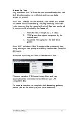
Page 51: ...imited by the lower of 1 ATS9360 Bus Throughput 3 5 GB s 2 PCI Express throughput supported by the motherboard 3 Sustained Throughput of the disk drive system AlazarDSO includes a Disk Throughput Benchmarking tool using which you can quickly and easily see how fast your disk drives are Accessed by clicking on Tools Benchmark Bus Files are saved as ATB format binary files and can automatically be c...

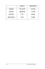
Page 52: ...44 ATS9360 User Manual CAPACITY WRITESPEED RAMDisk Few10 sGB 5 0GB s PCIeSSD Upto800GB 1 4GB s RAID SSD 2TB 2 8GB s RAIDHDDSAS 40TB 2 3GB s ...

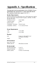
Page 53: ... throughput 4 GB RAM 100 MB of free hard disk space PCI Express revision 2 0a or higher Transceiver speed 5 Gbps Number of lanes 8 Compatibility mechanical x8 and x16 slots Compatibility electrical x1 x4 x8 and x16 slots Power Requirements 12V 1 3 A typical 3 3V 2 9 A typical Physical Size Single slot half length PCI card 4 2 inches x 6 5 inches Weight 250 g I O Connectors ECLK CH A CH B TRIG IN A...

Page 54: ... Input coupling DC Input impedance 50 1 Input protection 50 4V DC peak AC for CH A CH B and EXT only without external attenuation Acquisition Memory System Memory Size Uses on FPGA FIFO Record Length Software selectable with 64 point resolution Record length must be a minimum of 256 points There is no upper limit on the maximum record length Number of Records Software selectable from a minimum of ...

Page 55: ... Dynamic Parameters Typical values measured on the 200 mV range of CH A of a randomly selected ATS9360 Input signal was provided by a Marconi 2018A signal generator followed by a 9 pole 10 MHz band pass filter TTE Q36T 10M 1M 50 720BMF Input frequency was set at 9 9 MHz and output amplitude was 135 mV rms which was approximately 95 of the full scale input Input was averaged SNR 57 1 dB SINAD 56 6 ...

Page 56: ...ncies is dependent on the accuracy and stability of the 10 MHz Clock Referece input supplied by the user Triggering System Mode Edge triggering with hysteresis Number of Trigger Engines 2 Trigger Engine Combination OR Trigger Engine Source CH A CH B EXT Software or None independently software selectable for each of the two Trigger Engines Hysteresis 5 of full scale input typical Trigger sensitivit...

Page 57: ...range 2 5 V or TTL Input software selectable DC accuracy 10 of full scale input Input protection 8V DC peak AC without external attenuation Coupling DC only TRIG OUT Output Connector Used AUX I O Output Signal 5 Volt TTL Synchronization Synchronized to a clock derived from the ADC sampling clock Divide by 4 clock dual chan nel mode or divide by 8 clock single channel mode Certification and Complia...

Page 58: ...hese benchmarks are provided as a reference only and AlazarTech assumes no liability in case the computer you purchase behaves differently than what was observed in AlazarTech s laboratory Model Chipset Slot Throughput ASRock Extreme 11 Intel X79 PCIe x16 3 5 GB s ASUS P9X79 Intel X79 PCIe x16 3 5 GB s HP Z800 Intel Xeon PCIe x16 3 4 GB s HP Compaq 6200 Pro Intel i3 2100 PCIe x8 3 1 GB s Operating...

Page 59: ......

Page 60: ...ALAZAR TECHNOLOGIES INC 6600 Trans Canada Highway Suite 310 Pointe Claire QC CANADA H9R 4S2 Tel 514 426 4899 Fax 514 426 2723 E mail info alazartech com Web www alazartech com ...

Reviews: