background image

Page 20

Transducer Calibration should only be performed by an operator with the necessary calibration wheels or arm and weight
sets or by a calibration lab.  Mountz offers calibration services to perform this function. 

PTT calibrations are done in conjunction with a  PC Windows based Calibration Program.  The program is easy to use
and guides the user through the calibration steps.

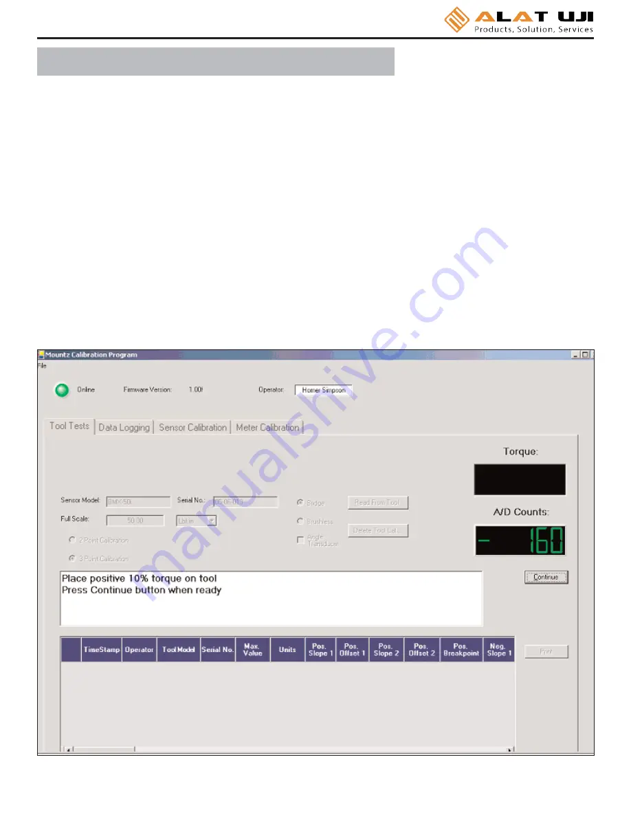
Once the program is started and connected to the PTT meter, a button 

"Start"

is provided to start the calibration.  All the

needed information must be entered in the appropriate text boxes.  This includes information such as the Sensor Model,
Serial Number, the Full Scale torque value, the units of calibration and the transducer type (Bridge or Brushless). Once
all required information is entered, the Start button is clicked, and its function changes to "Continue" as shown in figure
below and procedural information will be given in the large text box.  A 2-point calibration should work well in all but
exceptional circumstances.  

Once the calibration is complete the calibration data will be stored in a Mountz "Smart" transducer using the ARCII proto-
col.  For non-smart transducers calibration data will be stored in the PTT internal memory.  A sophisticated error 
correction algorithm assures that the data written to and retrieved from memory is always correct.

Once the calibration is complete, Torque Values will be displayed in the Torque Window allowing for verification of cali-
bration data points.

T r a n s d u c e r   C a l i b r a t i o n

Summary of Contents for PTT 2000

Page 1: ...Mountz Inc ISO 9001 2000 company P T T P T T Portable Torque Tester Operating Instructions 2000 ...

Page 2: ... Hz Easy to use Menu Structure Real Time Clock for time stamping of readings Six digit display USB interface to download readings to PC High Capacity Li Ion Batteries for long life 30 hrs with standard transducers and 16 hrs with brushless rotary Can connect to most mv v transducers and can store calibration data for up to 50 non smart torque sensors The 5VDC capability allows unit to be used with...

Page 3: ...Signal Negative output from bridge transducer 8 Not Used 9 Angle Lead TTL output from angle detector in angle transducer 10 Sensor Drive Used to detect transducers 11 Bridge Signal Positive output from bridge transducer 12 Shield 13 Angle Trail TTL output for angle lags Angle Lead by 90 degrees 14 5 Volt Angle Supply 15 Data for Smart Transducer Proprietary ARCII protocol for smart transducers fro...

Page 4: ...ter Units Mode Setup Main Menu 3000 Hz 2000 Hz 1500 Hz 500 Hz 200 Hz ozf in lbf in lbf ft kgf cm kgf m N m cN m Track Peak First Peak Audit Torque Angle Tolerance Auto Clear Angle Threshold T A Threshold First Peak Direction Clock Sub Menu Sub Menu Sub Menu Sub Menu Enter Enter Enter Enter Contrast ...

Page 5: ...erial Number 04 93 071 If an un calibrated transducer is connected then the Analyzer will display a screen as below Note The PTT supports Non Smart transducers and Non Mountz transducers Non smart transducers can be detected and can be calibrated in the internal memory The PTT will offer 2 choices It offers to calibrate or choose from a list of transducers stored in the internal memory Mountz PTT ...

Page 6: ... or Down key to toggle through Filter Units Mode and Setup 2 Press Enter key to select a choice Filter Units Mode Setup 1 Select Filter by highlighting and pressing Enter 2 Use the Scroll Up or Down key to toggle through the Filter options 3 Press Enter key to select a Filter Setting Filter Units Mode Setup 3000 Hz 2000 Hz 1500 Hz 500 Hz 200 Hz Selecting Filters Main Main Cancel ...

Page 7: ...pressing Enter 2 Use the Scroll Up or Down key to toggle through the Mode options 3 Press Enter key to select a Mode Setting 4 The Main or reading screen will display the value of the selected Mode Filter Units Mode Setup Selecting Mode Options Tolerance Auto Clear Angle Threshold T A Threshold First Peak Direction 1 Select Setup by highlighting and pressing Enter 2 Use the Scroll Up or Down key t...

Page 8: ...pe mechanical torque wrenches The PTT captures the point where the wrench clicks This peak may be used for operator training on correct use of the wrench Always apply torque smoothly to avoid false first peak readings See page 11 for setting up First Peak First Peak FPK 3000 Hz lbf in Menu Tool Tests FPK 3000 Hz 5 4373 lbf in Menu Tool Tests 7 6261 This mode is used to determine first movement or ...

Page 9: ...ggle through the Setup options 4 Press Enter key to select a setup setting for Tolerance Filter Units Mode Setup Selecting Tolerance 1 Press the Right or Left key to toggle between High and Low Tolerance 2 Use the Scroll Up or Down key to change the tolerance settings 3 Press Enter key once setting is complete 4 Press Main button to return to main display screen This function controls the method o...

Page 10: ... down to the Time selection 3 For Auto Clear use the Scroll Up or Down key to toggle between the selection of time between 1 5 seconds 4 Press Enter key once setting is complete 5 Press Main button to return to main display screen Tolerance Auto Clear Angle Threshold T A Threshold First Peak Direction This is for the Audit mode The default setting is 2 degrees but it can be set from 1 to 5 degrees...

Page 11: ...Main 1 Press the Menu Button 2 Use the Scroll Down key and select Setup by highlighting and pressing Enter 3 Use the Scroll Up or Down key to toggle through the Setup options 4 Press Enter key to select a setup setting for Torque Angle Filter Units Mode Setup Selecting Torque Angle 1 Press the Right or Left key to toggle between the three settings Angle Torque Allow Ratchet 2 Use the Scroll Up or ...

Page 12: ...hrough the sensitivity settings Low Medium High 2 Press the Right or Left key to move down to the Min Peak setting location 3 Use the Scroll Up or Down to set the Minimum Peak 4 Press Enter key once setting is complete 5 Press Main button to return to main display screen Page 11 Note First Peak Sensitivity This feature is provided for click wrenches It is not relevant for Mountz Break over or Cam ...

Page 13: ...irection Setting Direction BOTH Main 1 Press the Menu Button 2 Use the Scroll Down key and select Setup by highlighting and pressing Enter 3 Use the Scroll Up or Down key to toggle through the Setup options 4 Press Enter key to select a setup setting for Direction Filter Units Mode Setup Selecting Direction 1 Use the Scroll Up or Down key to toggle through the dIrection settings Both CW CCW 2 Pres...

Page 14: ...he Scroll Up or Down key to toggle through the Setup options 4 Press Enter key to select a setup setting for Clock Filter Units Mode Setup Selecting Clock 1 Use the Scroll Up or Down key to toggle through the digits for the date and time 2 Use the Right and Left key to move through the time and date sections 3 Press Enter key once setting is complete 4 Press Main button to return to main display s...

Page 15: ... unit Just press a key and the unit will power on When the unit has not been used for a designated time frame it will enter a Sleep Mode The unit features a processor that checks to see if a key pressed while it is in the Sleep Mode There is no significant drain on the batteries The PTT is powered using the high capacity Li Ion batteries for a long battery life The battery pack should last up to 3...

Page 16: ...nue Anyway Mountz has tested the product with both the Home version and Professional version of XP You will not get this message if you are installing under Windows 2000 8 9 10 The initial screen will appear The Online LED should be green and Torque values are displayed on the right side of the screen For most users the only Tab that will be used is the Tool Tests The other Tabs are used for Trans...

Page 17: ...yed on the right side of the screen For most users the only Tab that will be used is the Tool Tests The other Tabs are used for Transducer and Meter calibrations which should only be done by a certified calibration lab Image below is Torque Calibration screen 11 Image below is Meter Calibration screen ...

Page 18: ...he Tool Tests tab Enter the relevant information on this screen such as the Test Name which is the name by which the test will be identified on the PTT Then enter all required information on the screen because once the tool test is activated on the PTT no changes can be made with the units tolerances or other information There is a field for comments to include user specific information The transd...

Page 19: ...etrieves the results of a tool test after it has been run It will offer a change to add further notes to the test at this point The results will be saved in the PC in C PTT 2000 Tool Test Results Operator Folder where the Operator Folder will be the name of the Operator entered in the upper portion of the Tool Test Screen The results are stored in a csv file which can be opened in Excel or using a...

Page 20: ... by a colon and then the number of data points collected Stop ends the test This is required as some users may want to collect 10 data or others may want to collect 25 points or more Clear Memory allows the test points to be cleared in the meter itself The operator will be asked for confirmation before the action takes place This function should only be used if the readings have been downloaded to...

Page 21: ...lue the units of calibration and the transducer type Bridge or Brushless Once all required information is entered the Start button is clicked and its function changes to Continue as shown in figure below and procedural information will be given in the large text box A 2 point calibration should work well in all but exceptional circumstances Once the calibration is complete the calibration data wil...

Page 22: ...Mountz for those that require it as an optional item P T T C a l i b r a t i o n D a t a L o g g i n g This program is used for graphing the data This feature can be utilized to evaluate and confirm torque specifications in both production or R D environments When the graph first appears you can enlarge it by clicking on the Zoom Box which is the square box made up of dashed lines just to the righ...

Page 23: ...ta click the Graphing Icon that is on the spreadsheet the Torque and Angle will be plotted for you If you have your own Torque and Angle data you can just replace the example data with your own highlight it and click the Graphing Icon to plot it Angle Torque 6 3 64 21 3 62 36 3 63 137 4 34 153 3 99 167 4 05 182 4 23 196 4 30 211 4 13 225 3 74 240 3 99 254 4 32 269 4 52 283 4 31 298 4 01 313 4 18 3...

Page 24: ...supplied CD to the computer installed the PTT 2000 Interface program and installed the USB drivers Locate the Bootloader folder on your computer as shown below Select the Bootloader folder Run the Setup exe file by right clicking on it and choosing Open After installation the program will be located in the Mountz folder when you select All Programs ...

Page 25: ...ot load HEX file to device button Locate the HEX file update It will be in the Hex Files folder The file is named Mountz App hex This is the current application so there is no need to update but if the operator chooses he she can reload it to see how this feature works The process will take about 6 minutes as there is quite a lot of code in the product The status will be shown in the PTT Boot Load...

Reviews: