Alarm.Com Knowledge Base Verizon VoLTE Installation Manual Download Page 8

4. Place the module back plate on the wall at the desired mounting location, check for level, and mark the three

mounting holes and the wire access area (Figure 4). Leave room above the back plate to route the antennas.

5. Set the back plate aside and drill holes at the mounting and wire access area locations.

6. Use wall anchors where studs are not present and secure the back plate to the wall with the enclosed screws.

Wiring

To wire the module to the panel, do the following:

1. Remove panel AC Power and disconnect the backup battery. This is necessary to prevent damaging the panel or

module while making wiring connections.

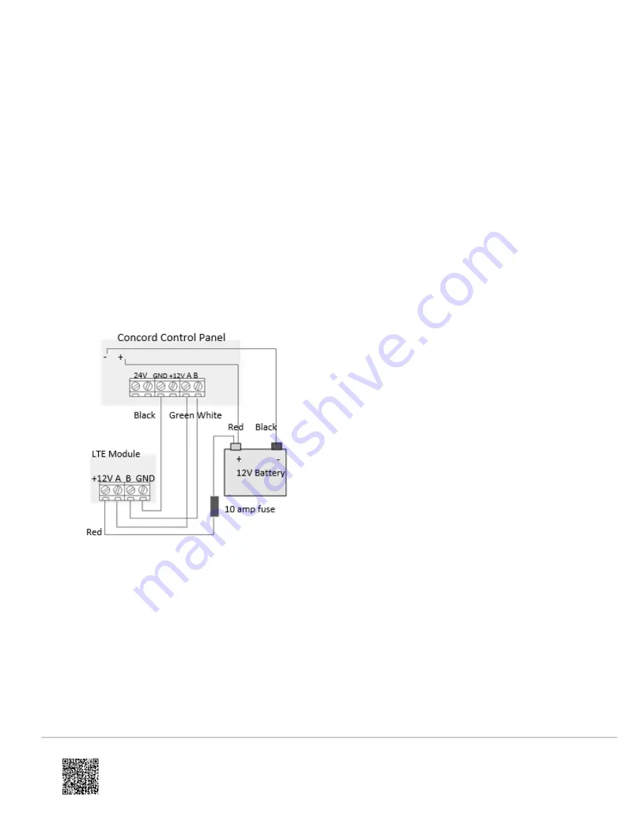
2. Wire the module to the panel bus and to the battery terminals for power as shown in

Figure 5

.

Note

: The module can also be powered off the SuperBus2000 two amp power supply (600-1019), but should not

be powered directly off the panel.

Figure 5: Wiring Terminals

3. If required, connect an input device to the module

Z1

and

ZCOM

terminals.

Case tamper switch installation (optional)

If the module is easily accessible, there is the option to add case tamper detection to activate an alarm or trouble
(depending on panel programming) when the cover is removed.

To install the tamper switch, see F

igure 6

and do the following:

1. Slide the reed switch into the plastic holder on the module back plate.

2. Connect a UL Listed reed switch (with a 2 KΩ EOL resistor 01-022) to the module zone input or to any unused

hardwired input on the panel.

https://answers.alarm.com/ADC/Partner/Installation_and_Troubleshooting/Panels/Interlogix_Concord/Interlogix_Concord_Inst…

Updated: Wed, 04 Mar 2020 15:12:44 GMT

8

Summary of Contents for Knowledge Base Verizon VoLTE

Page 1: ...liary 12 VDC power supply Status LEDs on the LTE module indicate bus and cellular network communications Compatibility The module can be used on Concord 4 0 and higher to enable Alarm com s interactiv...

Page 2: ...sing Case color Belgian gray Case material High impact ABS plastic Main module components Components description Component Function PWR LED Indicates module power status https answers alarm com ADC Pa...

Page 3: ...n MMCX antenna connectors The larger antenna connects to connector 1 the smaller antenna connects to connector 2 Module status LEDs Indicates communication with the LTE network report errors and signa...

Page 4: ...ashes every time a data packet is received from the panel L3 LTE communication LED L3 flashes every time a data packet is received from the LTE radio L4 LTE signal level LED L4 flashes zero to five ti...

Page 5: ...efore installation For more information see Account Creation 2 Turn off the Access Code Lock feature on the panel This feature must be off for the system to communicate with Alarm com 3 Installation i...

Page 6: ...ly connect the GND and 12V terminals After two minutes LTE status LED L4 will flash between one and five times to indicate the LTE signal strength level where five is the strongest signal Note Alarm c...

Page 7: ...proper operation Both antennas are pre installed for convenience The larger antenna will be connected to antenna connector 1 and the smaller antenna will be connected to antenna connector 2 3 For opti...

Page 8: ...own in Figure 5 Note The module can also be powered off the SuperBus2000 two amp power supply 600 1019 but should not be powered directly off the panel Figure 5 Wiring Terminals 3 If required connect...

Page 9: ...set to off for the system to communicate with Alarm com The module PWR LED should turn on After a few seconds the module BUS and AUTO LEDs should flash to indicate successful communication with the pa...

Page 10: ...ered The yellow and green LEDs indicate the message status The top LED is not used Red LED On The module is in range and registered with the network Off The module is out of range and not registered w...

Page 11: ...Blinks Blinks Module in range sending first message currently sending message 6 Blinks On Blinks Module out of range first message sent currently sending message 7 Blinks On Off Module out of range fi...

Page 12: ...f the panel and re insert it If the error is still observed try a different module Finally if that does not fix the problem try a different panel 2 then 4 The module provisioning process could not be...

Page 13: ...System Programming 0003 for module to communicate 8 If it persists the account may have been set up incorrectly Contact Alarm com Technical Support You will be asked to check the serial number of the...

Page 14: ...st be deleted before it can join a new network LED L3 green or yellow L3 flashes with every communication between the module and its radio unit in Idle Mode and with every communication with Alarm com...

Page 15: ...s The device you attempted to add into a Z Wave network was not successfully added 6 blink No Home ID present lasts until the module connects to Alarm com and is configured When the LTE module first c...

Page 16: ...unication with panel L3 Communication with Alarm com L4 Alternates two seconds on then two seconds off L5 Inactive Troubleshooting Testing Tips Check LTE status LED L1 to see if it is flashing any err...

Page 17: ...abled See Table 7 for a reference of the codes displayed Sensor 96 text Module serial number Table 7 Central Station Reporting Bits Reporting bit Description B Phone Test E Alarms F System trouble G S...

Page 18: ...rning the equipment off and on the user is encouraged to try to correct the interference by one or more of the following measures Reorient or relocate the receiving antenna Increase the separation bet...

Page 19: ...vice contains FCC ID RI7LE910SV IC 5131A LE910SV https answers alarm com ADC Partner Installation_and_Troubleshooting Panels Interlogix_Concord Interlogix_Concord_Inst Updated Wed 04 Mar 2020 15 12 44...

Reviews: