


MAINTENANCE
Eagle 20 03/09
Maintenance Section 5-16
© 2009 Alamo Group Inc.
MAINTENANCE
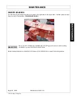
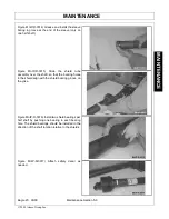
BLADE CARRIER INSTALLATION
Clean the taper and keyway on both the blade carrier and output shaft. Position carrier on the gear box output
shaft and install flat washer and 1" hex nut. Tighten the nut holding the blade carrier to minimum 450 ft.
pounds. Strike the carrier on the hub several times with a heavy hammer to seat the hub. Use a suitable
spacer over the nut to prevent damage to the nut and threads. Retighten the nut to 450 ft. pounds. Install and
spread cotter pin.
NOTE: After a few hours of operation always recheck blade carrier retaining nut torque.
Avoid personal injury. Do not work under cutter without support blocks to keep frame from
falling.
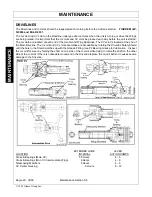
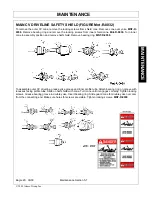
SLIP CLUTCHES
A slip clutch is incorporated on each outboard driveline. The slip clutches are designed to slip, absorb the
shock load, and protect the drivelines of the mower.
After the first hour of operation, the slip clutches should be checked for overheating. After this first check,
inspect weekly or anytime there is overheating. To adjust the slip clutch, tighten the spring bolts 1/8
(maximum) turn at a time. See
Figure Mnt-R-0018
for minimum dimension. DO NOT tighten springs beyond
1-15/32" length (from top of washer to pressure plate).
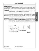
Each slip clutch should be checked periodically and adjusted to compensate for wear. The lining plates are 1/
8" thick when new. Replace after 1/32" wear. If the mower has been idle for an extended period of time, or in
wet weather, before operating check to be sure the friction lining plates are not rusted/frozen together. Should
this occur refer to the procedure described in the "Seasonal Clutch Maintenance" section on the next page.
There are four friction lining plates in the slip clutch. These should be checked weekly for oil or grease, wear,
and moisture which could cause corrosion on the drive plates.
Summary of Contents for Eagle 14
Page 6: ......
Page 9: ...Safety Section 1 1 2009 Alamo Group Inc SAFETY SECTION ...
Page 38: ......
Page 39: ......
Page 40: ......
Page 41: ......
Page 42: ......
Page 43: ......
Page 44: ......
Page 45: ......
Page 46: ......
Page 47: ......
Page 48: ......
Page 49: ......
Page 50: ......
Page 51: ......
Page 52: ......
Page 53: ......
Page 54: ......
Page 55: ......
Page 56: ......
Page 57: ......
Page 58: ......
Page 59: ......
Page 60: ......
Page 61: ......
Page 62: ......
Page 63: ......
Page 64: ......
Page 65: ......
Page 66: ......
Page 67: ......
Page 68: ......
Page 69: ......
Page 70: ......
Page 71: ......
Page 72: ......
Page 73: ......
Page 74: ......
Page 75: ......
Page 76: ......
Page 77: ......
Page 78: ......
Page 79: ......
Page 80: ......
Page 81: ......
Page 82: ......
Page 83: ...Introduction Section 2 1 2009 Alamo Group Inc INTRODUCTION SECTION ...
Page 87: ...Assembly Section 3 1 2009 Alamo Group Inc ASSEMBLY SECTION ...
Page 100: ......
Page 101: ...Operation Section 4 1 2009 Alamo Group Inc OPERATION SECTION ...
Page 151: ...Maintenance Section 5 1 2009 Alamo Group Inc MAINTENANCE SECTION ...
Page 153: ...MAINTENANCE Eagle 20 03 09 Maintenance Section 5 3 2009 Alamo Group Inc MAINTENANCE ...
Page 183: ......
Page 186: ...EAGLE 20 14 SOM 3 09 Printed in USA P N 00779092C ...