


OPERATION
Eagle 20 03/09
Operation Section 4-7
© 2009 Alamo Group Inc.
OPERA
T
ION
2.5 Tractor Hydraulics
The mower center section and each wing are positioned with hydraulic cylinders that are operated by the
tractor hydraulic pump. The tractor must have a minimum of 2 hydraulic control valves devoted to the mower
unless the tractor is fitted with a 3-spool control valve (extra equipment).
A 3-spool control valve is required if the tractor is equipped with a single valve and is recommended for those
with two valves so that the center section and each wing can be controlled independent of one another. Refer
to the Assembly Section of this manual for properly equipping the tractor with a 3-spool control valve. Tractors
equipped with three hydraulic ports can position the center section and each wing independently with no extra
equipment. If the tractor is equipped with only two hydraulic ports and a 3-spool control valve is not used, the
wings cannot be operated independently and will raise and lower at different speeds.
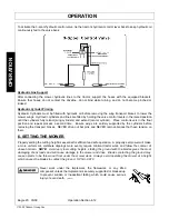
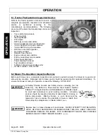
2.6 Front End Weight
A minimum of 20% total tractor weight must be maintained on the tractor front end at all times. Front end
weight is critical to maintain steering control and to prevent the tractor from rearing up while driving. If the
front end is too light, add weight until a minimum of 20% total weight is reached on the front tires. Front
weights and weight carriers can be purchased through an authorized tractor dealership.
OPS-U- 0005
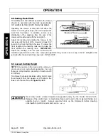
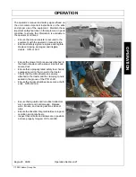
2.7 Power Take Off (PTO)
Depending on the unit, the mower is designed to operate at a PTO speed of 540 or 1000 RPM. Most tractors
operate at either 540, or a combination of 540 and 1000 RPM PTO speeds. The operating speed of the
mower and tractor can be determined by the number of splines on the driveline yoke and PTO output shaft.
Those operating at 540 RPM will have a 6-spline shaft and those operating at 1000 RPM will have a 21-spline
shaft.
Note: Refer to the tractor owner’s manual for instructions to change PTO speeds on models that
operate at more than one speed.
If operating an older model tractor where the tractor’s transmission and PTO utilize one master clutch, an
over-running clutch must be used between the PTO output shaft and the driveline of the mower. An
authorized tractor dealer can provide the over-running clutch and its installation if needed.
OPS-U- 0006_A
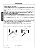
DO NOT
use a PTO adapter to attach a non-matching Implement driveline to a Tractor
PTO. Use of an adapter can double the operating speed of the Implement resulting in
excessive vibration, thrown objects, and blade and implement failure. Adapter use will also
change the working length of the driveline exposing unshielded driveline areas. Serious
bodily injury and/or equipment failure can result from using a PTO adapter. Consult an
authorized dealer for assistance if the Implement driveline does not match the Tractor PTO.
(S3PT-14)
Never operate the Tractor and Mower if the Implement input driveline is directly connected
to the Tractor transmission. Tractor braking distances can be substantially increased by
the momentum of the rotating Mower blades driving the Tractor transmission even though
the Tractor clutch has been disengaged. Install an over running clutch between the Tractor
PTO and the Mower driveline to prevent this potentially dangerous situation.
(S3PT-16)
Summary of Contents for Eagle 14
Page 6: ......
Page 9: ...Safety Section 1 1 2009 Alamo Group Inc SAFETY SECTION ...
Page 38: ......
Page 39: ......
Page 40: ......
Page 41: ......
Page 42: ......
Page 43: ......
Page 44: ......
Page 45: ......
Page 46: ......
Page 47: ......
Page 48: ......
Page 49: ......
Page 50: ......
Page 51: ......
Page 52: ......
Page 53: ......
Page 54: ......
Page 55: ......
Page 56: ......
Page 57: ......
Page 58: ......
Page 59: ......
Page 60: ......
Page 61: ......
Page 62: ......
Page 63: ......
Page 64: ......
Page 65: ......
Page 66: ......
Page 67: ......
Page 68: ......
Page 69: ......
Page 70: ......
Page 71: ......
Page 72: ......
Page 73: ......
Page 74: ......
Page 75: ......
Page 76: ......
Page 77: ......
Page 78: ......
Page 79: ......
Page 80: ......
Page 81: ......
Page 82: ......
Page 83: ...Introduction Section 2 1 2009 Alamo Group Inc INTRODUCTION SECTION ...
Page 87: ...Assembly Section 3 1 2009 Alamo Group Inc ASSEMBLY SECTION ...
Page 100: ......
Page 101: ...Operation Section 4 1 2009 Alamo Group Inc OPERATION SECTION ...
Page 151: ...Maintenance Section 5 1 2009 Alamo Group Inc MAINTENANCE SECTION ...
Page 153: ...MAINTENANCE Eagle 20 03 09 Maintenance Section 5 3 2009 Alamo Group Inc MAINTENANCE ...
Page 183: ......
Page 186: ...EAGLE 20 14 SOM 3 09 Printed in USA P N 00779092C ...