


MAINTENANCE
ABOOM 03/09
Maintenance Section 4-10
©2009 Alamo Group Inc.
MAINTENANCE
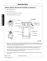
TIMBER CAT HEAD
Lubrication/Daily Checks (Figure Mnt-0007)
Lubricate the grease fittings on top of the blade bar
every 4 hours. See
Figure Mnt-0007
.
Every 8 hours, lubricate the cylinder grease fitting
through the top slot in the cover. See
Figure Mnt-
0007
. Ever y 8 ho urs, che ck all b olts an d nu ts fo r
proper tightness. T ighten any bolt or nut found to
be loose. Periodically check the hydraulic connec-
tions for oil leaks. V isually inspect the hos es for
damage a nd r eplace as necessary. Pe riodically
inspect bla de str oke adju stment by ru nning th e
head a t normal op erating speed ( 540 PT O) an d
checking t hat the u pper and lower b lades lin e-up
perfectly the instant of reversal (when they change
direction).
Improper adjustment is also indicated by an abnormally high shock load on the hydraulic system during blade
reversal. This is due to the h ydraulic cylinder reaching its stroke limit, causing the p ressure relief reversing
components to engage. Continuous operation in this mode will result in oil overheating and premature failure
of components. If the unit is improperly adjusted, follow the stroke adjustment procedures below.
Stroke Adjustment (Figure Mnt-0008)
Position the head in a safe a rea for op eration. If
necessary, b arricade the head t o p revent c ontact
while it is being operated.
Remove the cover a nd loosen the two jam nuts
(Item 1 ). See
Figure Mnt-0008
. Screw the two
spring bolt assemblies (Item 2) in toward the valve
push buttons. Start the unit and bring the speed up
to normal operating speed (540 PTO). Ch eck the
blade over lap. Adjust the spring b olt a ssemblies
(Item 2) , o ne b y o ne u ntil th e up per an d lowe r
blades p erfectly align in the in stant of re versal.
Never adjust the bolt as semblies to a point where
the hydraulic c ylinder r eaches it 's st roke limi t! This is indic ated by an abnormally h igh sho ck load on th e
hydraulic system due to the pressure relief reversing components being engaged. Continuous operation in this
mode will cause premature component failure and hydraulic oil overheat. Once proper adjustment has been
achieved, tighten the jam nuts (Item 1) and replace cover.
Summary of Contents for A-Boom
Page 7: ...Safety Section 1 1 2009 Alamo Group Inc SAFETY SECTION...
Page 48: ......
Page 49: ......
Page 50: ......
Page 51: ......
Page 52: ......
Page 53: ......
Page 54: ......
Page 55: ......
Page 56: ......
Page 57: ......
Page 58: ......
Page 59: ......
Page 60: ......
Page 61: ......
Page 62: ......
Page 63: ......
Page 64: ......
Page 65: ......
Page 66: ......
Page 67: ......
Page 68: ......
Page 69: ......
Page 70: ......
Page 71: ......
Page 72: ......
Page 73: ......
Page 74: ......
Page 75: ......
Page 76: ......
Page 77: ......
Page 78: ......
Page 79: ......
Page 80: ......
Page 81: ......
Page 82: ......
Page 83: ......
Page 84: ......
Page 85: ......
Page 86: ......
Page 87: ......
Page 88: ......
Page 89: ......
Page 90: ......
Page 91: ......
Page 92: ......
Page 93: ...Introduction Section 2 1 2009Alamo Group Inc INTRODUCTION SECTION...
Page 97: ...Operation Section 3 1 2009 Alamo Group Inc OPERATION SECTION...
Page 145: ...Maintenance Section 4 1 2009 Alamo Group Inc MAINTENANCE SECTION...
Page 161: ......


