AKG IVM 4500 User Instructions Download Page 8

2 Description

D

Diis

sp

plla

ay

y

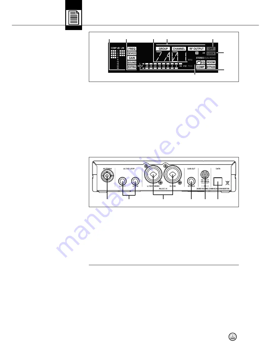
Fig. 2: LC display on 

transmitter front panel.

Refer to fig. 2.

R

Re

ea

arr  P

Pa

an

ne

ell

Fig. 3: Inputs and outputs

on transmitter rear panel.

Refer to fig. 3.

S

SP

PR

R  4

45

50

00

0  

B

Bo

od

dy

yp

pa

ac

ck

k  R

Re

ec

ce

eiiv

ve

err

C

Co

on

nttrro

olls

s

Refer to fig. 4.

The display indicates all operating parameters of the transmitter:

1

Compressor and limiter gain reduction.

2

Menus for frequency, transmitter name, input gain, audio processing, system
settings.

3

Submenus for Frequency Group, Subchannel, RF output.

4

OFF (red): Indicates the transmitter is off the air.

5

LOCK mode label (red): goes out in SETUP mode.

6

Alphanumeric display.

7

Audio input level bargraph and red PEAK LED

8

Audio functions: input mode, highpass filter, EQ, room simulation, compressor,
bypass.

In SETUP mode, the currently active setup parameter will be flashing.

1

ANTENNA:

BNC antenna output.

2

AUDIO LOOP L/CH1, R/CH2:

These two jacks are connected in parallel to the

AUDIO IN jacks and carry the unprocessed input signal.

3

AUDIO IN L/CH1/MONO, R/CH2:

Combined female XLR/1/4" jacks for feed-

ing in a stereo or mono signal. The ?" jacks accept both balanced and unbal-
anced cables.

4

LINE OUT STEREO:

This TRS ?" jack provides the processed audio signal. You

can feed this signal to an extra monitor amplifier for floor wedges, etc.

5

DC ONLY:

Locking DC input for connecting the included power supply.

6

DATA:

Interface for linking the transmitter to a HiQNet network for controlling the

transmitter using a computer and HUB 4000 Q.

The SPR 4500 bodypack receiver has been designed specifically for use with the 
SST 4500 transmitter and IP 2 earbuds. You may, however, connect other earbuds
to the receiver as well.
To power the receiver you can use either the two supplied dry batteries or the op-
tional BP 4000 battery pack from AKG.

1

Headphones output:

TRS mini jack.

2

Detented rotary control with integrated on/off switch:

Switches power to

the receiver on and OFF and sets the volume of the earbud signal.

3

Permanently attached flexible antennas.

4

Status LED

28

IVM 4500

1

2

6

4

5

3

1

2

3

4

5

6

7

8

Summary of Contents for IVM 4500

Page 1: ...ng the equipment MODE D EMPLOI p 42 Veuillez lire cette notice avant d utiliser le syst me ISTRUZIONI PER L USO p 62 Prima di utilizzare l apparecchio leggere il manuale MODO DE EMPLEO p 82 Sirvase le...

Page 2: ...eiver Menus 122 Basic Functions Figs A1 to A8 124 Advanced Functions Figs A9 to A26 128 Figs 7 to 12 Foldout Pages FCC Statement This equipment has been tested and found to comply with the limits for...

Page 3: ...ion Automatic Frequency Selection 6 Connect the earbuds to the receiver 7 Tune the transmitter to the same frequency you selected on the receiver sec tion Selecting Frequencies from the Preset Screen...

Page 4: ...rs s The following symbols are used in the menu diagrams Figs A1 through A26 on pages 121 to 136 24 IVM 4500 SETUP control on SST 4500 transmitter Jog switch on SPR 4500 receiver Long push appropx 2 s...

Page 5: ...he microphone inputs away from power lines of any type If you use cable ducts be sure to use separate ducts for the audio lines 10 Clean the equipment with a moistened not wet cloth only Be sure to di...

Page 6: ...using the earbuds if they are causing great discomfort or in fection 1 The power supply will draw a small amount of current even when the equip ment is switched off To save energy disconnect the power...

Page 7: ...RA 2 W passive wideband directional antenna RA 4000 W passive wideband omnidirectional antenna PSU 4000 central power supply HUB 4000 Q network interface MK PS antenna cables Front panel mounting kit...

Page 8: ...ected in parallel to the AUDIO IN jacks and carry the unprocessed input signal 3 AUDIO IN L CH1 MONO R CH2 Combined female XLR 1 4 jacks for feed ing in a stereo or mono signal The jacks accept both b...

Page 9: ...ating parameters of the receiver 1 Menus for Frequency Group Subchannel number of clean channels 2 Alphanumeric display 3 Menus for preset frequency frequency in MHz squelch 4 RF level meter limiter i...

Page 10: ...s microphone channels 1 Unscrew the four rubber feet 1 from the transmitter bottom panel 2 Unscrew the two fixing screws 2 from each side panel 3 Use the fixing screws 2 to screw the short bracket 3 t...

Page 11: ...thing you need to do is select a Pre set Read on in section Automatic Frequency Selection When powering up again later the receiver will automatically come on in LOCK mode The display will indicate t...

Page 12: ...nu The currently active frequency starts flashing 2 Confirm the selected frequency or use the arrow keys to select a different GROUP 3 Confirm the selected frequency 4 Program the transmitter to the s...

Page 13: ...signal Connect the stereo monitor outputs on your mixer to the two AUDIO IN jacks on the transmitter rear panel If your mixer can provide two different monitor signals e g AUX 1 for the soloist s mic...

Page 14: ...us screens Preset comes up only if a Preset has been saved Carrier frequency shown as a Subchannel number within a Frequency Group Frequency Carrier frequency in MHz This screen is always available ev...

Page 15: ...switch CW or CCW as many times as needed to call up the AUTO and CH labels on the display Select the desired Frequency Group The frequency search starts automatically The FREE tag incidactes how many...

Page 16: ...m 125 Hz to 250 Hz for added clarity Recommended for repairing indifferent muddy sound SOFT 1 3 Upper mid attenuation between 3 4 kHz and 6 8 kHz for a mel low sound Recommended for repairing excessiv...

Page 17: ...can call up the following details about your transmitter in this order Firmware version e g F 3 09 Frequency band e g B 5 E5 Preset version e g P 1 00 Audio preset version e g A 03 00 You can reset al...

Page 18: ...urn the jog switch CW to call up the frequency menu 1 You can select the desired frequency in 25 kHz increments 2 Save your setting SAVE Y The selected frequency will be added to your CUE GROUP 1 In C...

Page 19: ...volume of both channels is the same 3 To save your selection press the Jog switch briefly You can call up the balance screen even in LOCK mode by pressing the Jog switch briefly You can set and save t...

Page 20: ...5 Transmitter is tuned to different frequency than receiver 6 Receiver batteries are not in serted properly 7 Receiver batteries battery pack dead 8 Transmitter is too far away from receiver or squel...

Page 21: ...ter digitally controlled Audio processor 24 bit DSP Audio outputs AUDIO LOOP 2 x jacks directly connected to audio input LINE OUT TRS jack connected to audio section output 0 dBV max HP OUT 18 Hz to 2...

Reviews: