


2 Description
IIn
nttrro
od
du
uc
cttiio
on
n
U
Un
np
pa
ac
ck
kiin
ng
g
O
Op
pttiio
on
na
all
A
Ac
cc
ce
es
ss
so
orriie
es
s
S
SS
ST
T 4
45
50
00
0
S
Stta
attiio
on
na
arry
y T
Trra
an
ns
sm
miitttte
err
F
Frro
on
ntt P
Pa
an
ne
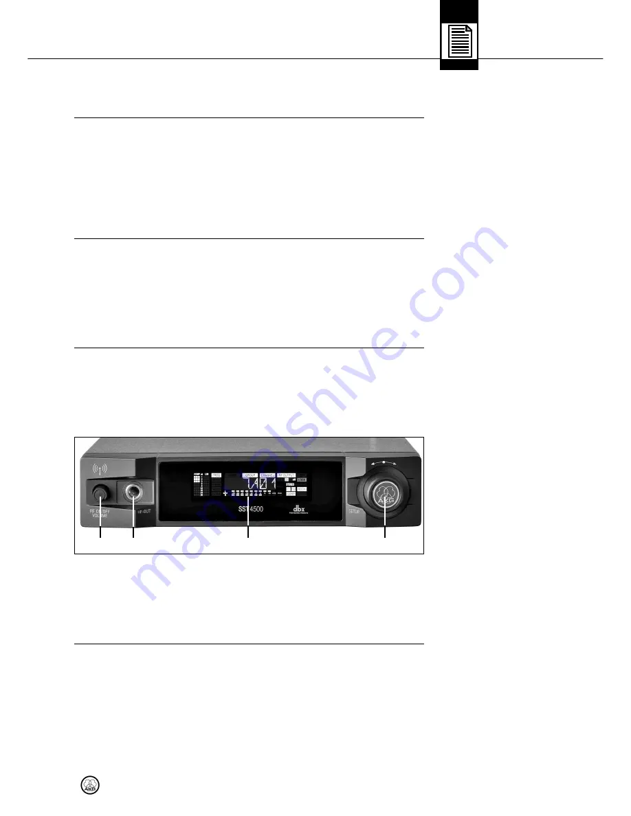
ell
Fig. 1: Transmitter front
panel and display.
Refer to fig. 1.
Thank you for purchasing an AKG product. This Manual contains important instruc-
tions for setting up and operating your equipment. Please take a few minutes to
read the instructions below carefully before operating the equipment.
Please
keep the Manual for future reference. Have fun and impress your audience!
•
1 SST 4500 stereo transmitter
•
1 SPR 4500 bodypack stereo receiver
•
1 pair of IP 2 earbuds with 3 pairs of ear molds
•
1 rod antenna
•
1 rack mounting kit
•
1 power supply
•
2 AA size dry batteries
•
Check that the packaging contains all of the items listed above. Should any of
these items be missing, please contact your AKG dealer.
•
SPC 4500 wideband antenna combiner
•
SRA 2 W passive wideband directional antenna
•
RA 4000 W passive wideband omnidirectional antenna
•
PSU 4000 central power supply
•
HUB 4000 Q network interface
•
MK PS antenna cables
•
Front panel mounting kit for supplied antenna 0110E01890
•
BP 4000 2.4-V rechargeable battery pack
•
CU 4000 charger for 2 receivers or BP 4000 battery packs
The SST 4500 is a stationary stereo transmitter designed to transmit a mono, stereo,
or dual-channel signal to the SPR 4500 bodypack stereo receiver. It allows you to
select one of 1200 frequencies within a 30-MHz band. In addition, it provides an in-
tegrated compressor, limiter, highpass filter, and a dedicated binaural room simu-
lator. You can use the transmitter as a standalone unit or install it in a 19" rack using
the supplied rack mounting kit.
1
RF ON/OFF VOLUME:
Combined pushbutton switch for activating/deactivat-
ing RF power and rotary volume control for the headphone output.
2
HP OUT:
TRS 1/4" jack for connecting a pair of headphones. The signal is iden-
tical to the audio signal fed to the RF section.
3
SETUP:
Adjusts the transmitter parameters.
4
Color code:
Replaceable ring for marking the transmitter.
5
Display:
Seenext page.
27
IVM 4500
1
2
3
4