Standard mode:
Settings:
1 = Master/Slave = M
2 = Bitrate = 1000000(1.019.642)
3 = Databits = 8
4 = CPOL = 1
5 = CPHA = 0
6 = Data Control =
N
7 = Data Poll*10ms = 10
8 = Flow Control = N
9 = RTS Protocol = 0
In this mode the SPI interface is absolutely transparent. I.e. no data will be sent to the SPI-Slave as long as
no data are being received. The user has got the option to control the data flow by himself. Therefore, in
order to receive data from the SPI-Slave, there must first be a connection available via the TCP/IP and it is
necessary to send data from the Client (Remote). Such data will then be directly sent to the SPI–Slave.
Example:
There is a TCP/IP connection available and the SPI-Slave has to return on byte “0x33” in response to a 3
byte query e.g. “0x01, 0x00, 0x33“.
The data which are marked by “nn” do not include any relevant information. However, it is necessary to keep
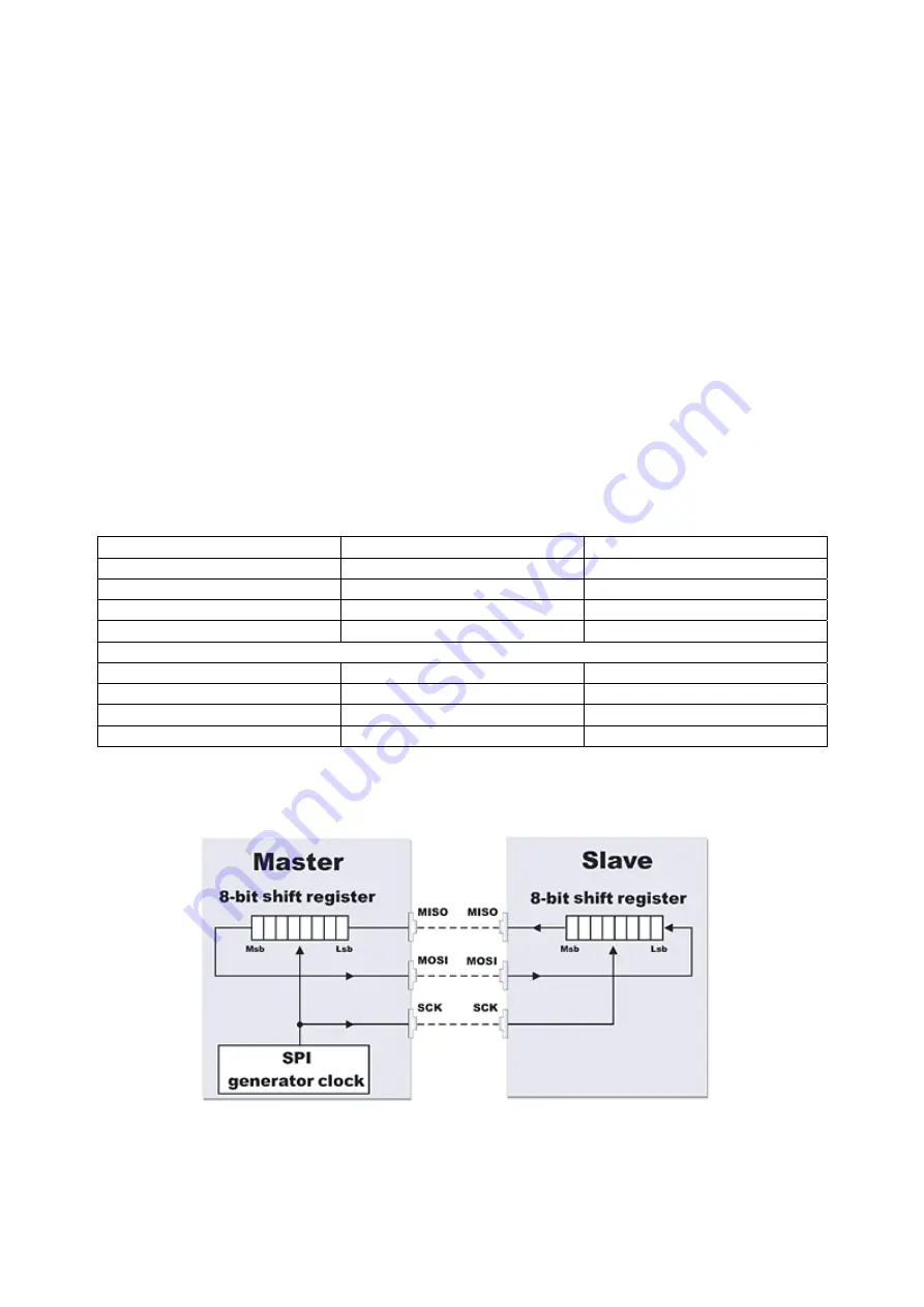
in mind that one bit is being received for each bit which is leaving the Master. (Refer to illustration)
Remote XT-PICO
SPI-Slave
0x01, 0x00, 0x33 ->
0x01, 0x00, 0x33 ->
->
0xnn, 0xnn, 0xnn <-
0xnn, 0xnn, 0xnn <-
<-
0xnn ->
0xnn ->
->
0x33 <-
0x33 <-
<-
or
(if the SPI–Slave is rapid enough)
0x01, 0x00, 0x33, 0xnn->
0x01, 0x00, 0x33, 0xnn ->
->
0xnn, 0xnn, 0xnn ,0x33 <-
0xnn, 0xnn, 0xnn, 0x33 <-
<-
Summary of Contents for XT-PICO-XXL
Page 1: ...XT PICO XXL DesignGuide V1 1...
Page 6: ...5 Dimensions 22 mm 2mm 2mm 32 mm 24 mm Bottom View...
Page 9: ...Connecting plan...
Page 10: ...7 Schematics RS232...
Page 11: ...RS485...
Page 12: ...SPI...
Page 13: ...I2C...
Page 14: ...SD CARD...
Page 15: ...LCD DISPLAY SPI...
Page 16: ...LCD DISPLAY 4BIT...
Page 17: ...Dataflash SPI...
Page 18: ...POE PowerOverEthernet Note The POE module is available at AK NORD Order number AK9050...


