background image

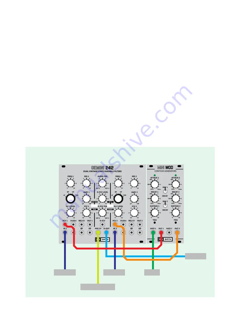
For this patch we are using the Gemini in DUAL Mode, so the Dual switch is down and the Invert switch is up (off).

In this example we are looking at mixing and filtering two different audio sources to a single output. The audio inputs can be 

anything - VCO’s, full synth voices, noise or external audio - however they both need to be at Eurorack Modular levels - i.e. 10V 

p/p.

The two audio inputs are patched to inputs IN 1 and In 2 respectively, and here we are using the central Mixing bus to cross 

fade and combine the two signals into a single audio output, which is fed to the D-OUT jack.

We can cross fade from VCF 1 to VCF 2 either manually with the AUDIO MIX control (when no cable is patched to the MIX CV 

input), or we can use a CV voltage of 0 to +5V, patched to the MIX CV jack, to pan between the two filters. The AUDIO MIX 

control acts as an attenuator for this control voltage, so simply set it to a position that gives the desired panning range.

We have also shown a dual envelope generator to control the cutoff of each filter individually, obviously this is optional and 

and is shown as one of  many modulation possibilities.

Please note that even with the filter cutoff’s set full open and the resonance set to zero there is still some colouration and 

distortion to the resulting sound due to the filter circuitry, and in many cases this is desirable, don’t expect this to be  a super 

low distortion Pro-Audio mixing solution...  It is shown as a combined mixing and filtering modular patch which will add some 

character too!


Note:  The numbers used to illustrate control knob positions do not relate to the markings on the module itself, but are simply a scale from zero to 10 with 5 

being the control centre position. For attenuverters the control positions are  -10 to +10, with zero being centre position for the control knob.

GEMINI 2412 - PATCHING EXAMPLES

Gate 1

AUDIO 1

AUDIO 2

EXTERNAL  CV

OUTPUT

0

5

3

8

8

1

0

5

2

5

5

0

5

5

5

10

0

0

LP

LP

DUAL

VCF 2

0

5  - DUAL Mode - mixing and filtering two audio input sources

Mixing and filtering two audio input sources

Summary of Contents for Gemini 2412

Page 1: ...ix of VCF1 OUT 1 against VCF2 OUT 2 is controlled by the setting of the Audio Mix control with the output routed to the D OUT jack Dual Parallel INVERTED Mode this is the same as Dual mode however the...

Page 2: ...Cascade switch This connection is made using the internal switch on the IN 2 jack socket and is connected if no jack socket is connected but if a patch cable is insered into IN 2 then this connection...

Page 3: ...ance VCF 2 Frequency Vary 2 Control VCF 2 Mode Freq CV 2 Level INPUT 2 Level VCF 2 Output VCF 2 RES CV 1V Oct Input VCF 2 FCV IN VCF 2 Input VCF 2 LP Out VCF 2 BP Out VCF 2 HP Out 6 7 5 4 3 14 13 12 1...

Page 4: ...with this control setting so in this case it acts as a offset control 5 VCF MODE Switch This selects the filter type that is routed to the OUT jack 7 and to the central mixing bus 6 INPUT Level This i...

Page 5: ...rates from a VCO The accepted signal range is 5V to 5V Any voltages higher or lower than this will be capped to 5 or 5V Maximum permissible voltage to this input is 12V 13 BP Output This is the Band...

Page 6: ...cted in Dual Parallel or Cascade Series DUAL VCF 1 input is normalised to VCF 2 input so that the same signal is presented to both filters and the AUDIO MIX control 15 cross fades between the outputs...

Page 7: ...re the two VCF s are mixed together This is the only output that combines the mix of VCF 1 and VCF 2 so to use the DUAL CASCADED and DUAL INVERTED modes this jack must be used as the output All of the...

Page 8: ...f oscillation jumpers There are a few points to note about self oscillation mode 1 Because we have to force the circuitry into self oscillation the resulting signal level is quite high around 19V p p...

Page 9: ...ale buffer can be a useful addition if the self oscillation mode is used often and accurate 1V Octave scaling is required it allows scaling to be adjusted from the front panel without having to remove...

Page 10: ...of the Envelope CV so it will close down rather than open up the filter cutoff point The bass voice is fed to Gemini VCF 2 from the lower VCO This time on the Gemini we are using the OUT 2 jack and th...

Page 11: ...F 1 and VCF 2 are set to Band Pass and have quite a large amount of resonance added we get some classic vowel sounds and sweeping between the filters gives interesting tonal variation Try different se...

Page 12: ...D FCV Mix control at mid point so that the D FVC control signal is being sent equally to VCF 1 and VCF 2 We have also included a variant on this patch lower picture which shows the inverse output from...

Page 13: ...lockwise from zero to 10 fades between single 12dB LP configuration VCF 1 only and 24dB configuration VCF 1 and VCF 2 cascaded in series You will not that the 24dB setting sounds duller and less brigh...

Page 14: ...ired panning range We have also shown a dual envelope generator to control the cutoff of each filter individually obviously this is optional and and is shown as one of many modulation possibilities Pl...

Page 15: ...lly a Linear or Hybrid suppy Also there are a few Eurorack modules which are badly behaved and can introduce noise back onto onto the Eurorack power rails too the way to find these is to disconnect al...

Page 16: ...s then test tracking again E Scale 2 This trimmer adjusts the 1V Octave tracking of VCF 2 Turning it anti clockwise reduces shortens the scaling and turning clockwise increases scaling Note For use by...

Reviews: