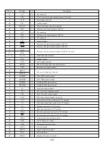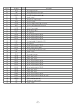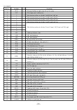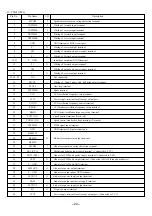
– 26 –
MD TEST MODE
Test Mode
The operations are displayed by LCD of the remote controller. The keys of the main unit and remote controller can control shifts between operations.
* TEST MODE will ignore any abnormalities during operation. Plug off the power supply once any abnormalities are detected.
* HOLD switch of the remote controller will function in TEST MODE.
Test Mode
1. How to activate and cancel Test Mode
(1) How to activate
Turn ON the power supply (set batteries) while pressing “VOL –” keys of both the main unit and remote controller.
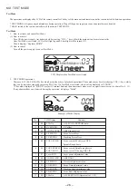
Once Test Mode is activated, LCD will all light up and EL backlight will be turned ON.
Then it displays “Engineer MODE”.
(2) How to cancel
Turn off the power supply to cancel Test Mode.
LCD Display when Test Mode is activated
2. TEST MODE operations
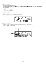
There are 0~13 (00~0d) Test Modes, which are in the order of playback operations. These modes may be selected using VOL+/– keys, while
they can be started or stopped by pressing PLAY key. If a Test Mode is selected, a data will be displayed in “$XXXX”.
* The values displayed in “$XXXX” are just IC internal data and their numerical values are of no significance (except for that of No. 0, 13).
If any abnormalities were detected during the operation, it displays “Failed”.
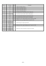
Example of Mode Display
No.
LCD Display
Contents
0
00
050c Xe
ALL SV ON (EEPROM data)
1
01
VC $XXXX
VC offset
2
02
ABCD $XXXX
ABCD input offset
3
03
FE $XXXX
Focus Error offset
4
04
TE $XXXX
Tracking Error offset
5
05
FOCUS CHK
Focus search (Focus servo OFF)
Spindle Rough Servo
6
06
FOCUS SRCH
Focus search, Spindle rough servo
FOCUS ON!
Focus servo ON during DISC IN
7
07
Laser $XX
Laser power adjustment value
8
08
ABCD G $XX
ABCD AGC
9
09
EF $XXXX
Traverse adjustment value
10
0A
FG $XXXX
Focus Gain adjustment value
11
0B
TG $XXXX
Tracking Gain adjustment value
12
0C
FB $XXXX
Focus Bias adjustment value
13
0D
050c Xe
ALL SERVO ON (Operate all of 1-12)

