background image

American Industrial Systems – Marine Rugged Display Computer User Guide

Page 2

The information contained in this document is subject to change without notice. This
document contains proprietary information that is protected by copyright © 2013
American Industrial Systems. All rights are reserved. No part of this document may be
reproduced, translated to another language, stored in a retrieval system, or transmitted by
any means, electronic, mechanical, photocopying, recording, or otherwise, without prior
written permission. Windows is a registered trademark of Microsoft, Inc. Other brand or
product names are trademarks of their respective holders.

American Industrial Systems, Inc.

http://www.aispro.com

The test results show that this device meets FCC rules. Those limits are set to protect residential areas
from harmful emissions from the devices. This device will produce, use and radiate radio frequency
energy. In addition, failure to follow the user manual in order to install or use this device might produce
harmful interference with radio communication.  Foregoing this information does not guarantee that this
type of harmful interference will not occur in some special instances. The interference caused by this
device to radio or television signals may be verified by turning the device on and off. Any changes or

modifications to this TFT LCD would void the user’s authority to operate this device.

Important Recycle Instruction:

Lamp(s) inside this product contains mercury. This product may contain other electronic waste that can be
hazardous if not disposed of properly. Recycle or dispose in accordance with local, state, or federal Laws.
For more information, contact the Electronic Industries Alliance at WWW.EIAE.ORG. For lamp specific
disposal information check WWW.LAMPRECYCLE.ORG

Summary of Contents for DNVMR10ID3S-M2-5RT

Page 1: ...Exclusion of Accident Liability Obligation 4 2 3 Liability Limitation Exemption from the Warranty Obligation 4 3 Safety Instructions 5 3 1 Electrostatic Discharge ESD 6 3 2 Grounding Methods 6 4 User Guide Marine Rugged Display Computer 10 4 DNVMR10ID3S M2 5RT 12 DNVMR12ID3S M2 5RT 15 DNVMR15ID3S M2 5RT 17 DNVMR17ID3S M1 5RT 19 DNVMRW19ID3S A2 5RT 24 DNVMRW24ID3S A1 5RT ...

Page 2: ...al areas from harmful emissions from the devices This device will produce use and radiate radio frequency energy In addition failure to follow the user manual in order to install or use this device might produce harmful interference with radio communication Foregoing this information does not guarantee that this type of harmful interference will not occur in some special instances The interference...

Page 3: ...Product Description 11 4 1 General Information 11 4 2 Features 11 5 Basic Construction 12 6 Touch Screen Solution 13 6 1 Introduction to Five Wire Resistive Touch Screen 13 6 2 Introduction to SAW Touch Screen Error Bookmark not defined 7 Installation 14 7 1 General Installation 14 7 2 VESA Wall Mount Installation 17 7 3 Important Installation Precautions 18 7 3 1 Brightness Control Knob Precautio...

Page 4: ...Color Item Menu 29 8 2 4 5 PIP Control Item Menu 31 8 2 4 6 Main Display Item Menu 33 8 2 4 7 PIP Display Item Menu 34 8 2 4 8 Audio Item Menu 35 8 2 4 9 Reset Item Menu 36 8 3 Simple Troubleshooting Guide 37 9 Appendix 38 9 1 Cleaning the Monitor 38 9 2 Disclaimer and Troubleshooting 39 9 3 Supported Modes 40 9 4 Touch Screen Driver Installation 43 9 5 RMA Return Material Authorization Service 44...

Page 5: ...does not involve any guarantee on the part of American Industrial Systems Inc regarding technical processes described in the manual or any product characteristics specified in the manual American Industrial Systems Inc does not accept any liability for any printing errors or other inaccuracies in the manual unless it can be proven that American Industrial Systems Inc is aware of such errors or ina...

Page 6: ...t out parts that could result in a risk of fire or electric shock Never spill liquid of any kind on the product Do not attempt to service this product yourself as opening or removing covers may expose you to dangerous voltage points or other risks and will void the warranty Refer all servicing to qualified service personnel Unplug this product from the wall outlet and refer servicing to qualified ...

Page 7: ...ms Inc Maintenance or repair on the open unit may only be operated by specialists or technicians qualified and authorized by American Industrial Systems Inc who are familiar with the related hazards When accessing the internal components users must switch off the unit and disconnect it from the power source Only original accessories or suggested optional parts approved and supplied by American Ind...

Page 8: ...5 FCC Statement This equipment has been tested and found to comply with the requisites for a Class A digital device pursuant to Part 15 of the FCC Rules These limits are designed to provide reasonable protection from harmful interference when the equipment is operated in commercial environments This equipment generates uses and radiates radio frequency energy and if it is not installed and used in...

Page 9: ...American Industrial Systems Marine Rugged Display Computer User Guide Page 9 2 7 Important LCD Information ...

Page 10: ...l Systems Marine Rugged Display Computer User Guide Page 10 3 0 Packaging List Item Description Note 1 User Manual 1 CD for Touchscreen Drivers Tools 1 Standard VGA Cable D SUB 15pin Male to 15pin Male 1 8m 1 Power Cord ...

Page 11: ...ional optical bonding wide view angles and full range dimming The touchscreen panel is fully integrated with the computer to reduce system integration costs and minimize required footprint Full support is provided for wide range of panel resolutions in order to meet specific requirements of many different marine applications AIS professional high quality design provides marine users with reliable ...

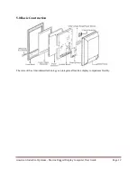
Page 12: ...American Industrial Systems Marine Rugged Display Computer User Guide Page 12 5 0 Basic Construction The state of the art modulated technology can integrate all marine display components flexibly ...

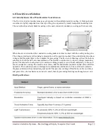
Page 13: ...epresentation of the position touched The controller digitizes these voltages and transmits them to the computer for processing The five wire technology utilizes the bottom substrate for both X and Y axis measurements The flexible coversheet acts only as a voltage measuring probe This means the touchscreen will continue working properly even with non uniformity in the cover sheet s conductive coat...

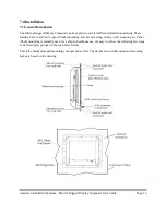
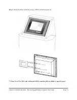
Page 14: ...tion methods These include but not limited to panel flush mounting bracket mounting ceiling wall mounting etc Panel flush mounting is normally used for a ship s wheelhouse use it s easy to follow the following few steps to fix the display product in the customer s fixture Check the mechanical and mounting concepts below first The fixture cut out dimension and mounting holes are based on the drawin...

Page 15: ...ne product on the fixture console from the front and screw in the four M6 x 30 mm black bolts with nuts Step 2 Use M4x 15mm bolts to drill through the fixture into the mounting holes on the rear side of the IP65 front bezel The quantity of mounting screws is based the size of your specific monitor ...

Page 16: ...l Systems Marine Rugged Display Computer User Guide Page 16 Step 3 Check the finished mounting concept DNV certification approved Please Note The VESA and wall mount with the mounting kit is available by special request ...

Page 17: ...dard which defines a physical mounting interface for flat panel monitors It also corresponds with the standards of flat panel monitor mounting devices such as walls and table arms The VESA mounting interface is located on the back of your monitor To mount the monitor on an UL listed certified swing arm or other mounting fixture follow the instructions included with the mounting fixture to be used ...

Page 18: ...t placement Please make sure to correctly install the monitor in order to protect the knob 7 3 2 Cable Connection Precaution Make sure to use qualified shielded signal cables to connect the Marine products These cables include the RGB DVI RS232 LAN and USB cables and should be connected as marked below For DC power connection please make sure the power cable is tightly connected by the two screws ...

Page 19: ...erminal block is to be secured so that the cable does not disconnect from the terminal AC Standard 90V to 265V power input is also available for AC version options Use standard power cords to connect to the AC power inlet RS232 serial port for touch and remote control connection Connect Standard D SUB 9pin connector from your system to the monitor to control the touchscreen Be sure the appropriate...

Page 20: ...riendly interface used to toggle between different display functions as well as a dimming VR knob The on screen display OSD contains several functions that will let the user adjust or set up the display to their preferred setting It also supplies special Hot Keys such as clicking two keys together for easy image flipping and auto color balance adjustment ...

Page 21: ...es the OSD if pressed at the Menu level 8 2 2 Auto Adjustment Function Controls When OSD Menu and PIP is disabled press to perform the screen Auto Adjustment When PIP is enabled it switches the image in the Main Display to the PIP Display and vice versa by pressing again When image side by side PAP mode is active the SWAP key exchanges the left and right displays 8 2 3 Source Function Controls Whe...

Page 22: ...splay Computer User Guide Page 22 8 2 4 OSD Menu Functions After powering on press to enter the OSD Menu The OSD Menu There are 9 functions in the OSD Menu for selection Each function can be easily selected by using the navigation keys as follows ...

Page 23: ...American Industrial Systems Marine Rugged Display Computer User Guide Page 23 8 2 4 1 Display Item Menu ...

Page 24: ...American Industrial Systems Marine Rugged Display Computer User Guide Page 24 8 2 4 2 Image Item Menu ...

Page 25: ...American Industrial Systems Marine Rugged Display Computer User Guide Page 25 ...

Page 26: ...n the screen In Fill mode the input image is stretched compressed to fill the available display area o In Aspect mode the input image is stretched compressed by the same horizontal and vertical factor Please Note in Auto Adjust o The only button available is SELECT Note this may change the values of Phase and Clock and there is no undo feature ...

Page 27: ...American Industrial Systems Marine Rugged Display Computer User Guide Page 27 8 2 4 3 Position Item Menu ...

Page 28: ...American Industrial Systems Marine Rugged Display Computer User Guide Page 28 ...

Page 29: ...American Industrial Systems Marine Rugged Display Computer User Guide Page 29 8 2 4 4 Color Item Menu ...

Page 30: ...American Industrial Systems Marine Rugged Display Computer User Guide Page 30 ...

Page 31: ...American Industrial Systems Marine Rugged Display Computer User Guide Page 31 8 2 4 5 PIP Control Item Menu ...

Page 32: ...d into two parts The left window displays the Main output while the right window displays the PIP output Each window is half the size of the total display area Each input is scaled down to fit the window Please Note in PIP mode The PIP screen can assume any position on the screen This can be achieved by adjusting both Horizontal and Vertical positions ...

Page 33: ...an Industrial Systems Marine Rugged Display Computer User Guide Page 33 8 2 4 6 Main Display Item Menu Press and to select the Main Display source including VGA DVI Composite and S Video mode Press to select ...

Page 34: ...can Industrial Systems Marine Rugged Display Computer User Guide Page 34 8 2 4 7 PIP Display Item Menu Press and to select the PIP display source including VGA DVI Composite and S Video mode Press to select ...

Page 35: ...American Industrial Systems Marine Rugged Display Computer User Guide Page 35 8 2 4 8 Audio Item Menu ...

Page 36: ...American Industrial Systems Marine Rugged Display Computer User Guide Page 36 8 2 4 9 Reset Item Menu ...

Page 37: ...warning messages on your LCD screen this means that the LCD display cannot receive a clean signal from the computer graphics card Below are three kinds of Warning Signals Please check the cable connections or contact your local dealer or our service center for more information 1 No Signal a This message means that the LCD display has been powered on but it cannot receive any signal from the comput...

Page 38: ...e display area is highly prone to scratching Do not use Ketone type material ex Acetone Ethyl Alcohol Toluene Ethyl Acid or Methyl Chloride to clear the panel It may permanently damage the panel and void the warranty 5 If it is still not clean enough apply a small amount of non ammonia non alcohol based glass cleaner onto a clean soft lint free cloth and wipe the screen 6 Don t use water or oil di...

Page 39: ...the screen and or case of the monitor Seller will not be liable for damage resulting from the use of any ammonia or alcohol based cleaner Troubleshooting If your monitor fails to operate correctly consult the following chart for possible solutions before calling for repairs For more information please go to the website http www aispro com and contact technical support to help resolve your issue Yo...

Page 40: ...American Industrial Systems Marine Rugged Display Computer User Guide Page 40 9 3 Supported Modes ...

Page 41: ...d Codes Optional Description ex DOWN 0x04 0x12 0x02 0xE8 Function par1 par2 par3 par4 Function DOWN down key Par1 0x04 length cannot be modified by user Par2 0x12 inquiry code cannot be modified by user Par3 0x02 command code can be modified by user Par4 0xE8 check sum cannot be modified by user ...

Page 42: ...mination The stronger the ambient light is the brighter the LCD will appear As a result the modified LCD is viewable under some lighting conditions including but not limited to direct sunlight The following table shows the outdoor readability for the Marine Rugged Display models Outdoor Readability Screen Size 10 4 15 19 23 24 Ambient Light nit 10 000 30 000 80 000 10 000 30 000 80 000 10 000 30 0...

Page 43: ...ower on the computer 2 Make sure that the USB cable is connected to the computer 3 Be sure that your EWF is disabled If your EWF is enabled please disable the EWF by using the EWF Manager command 4 Once the EWF is disabled click on the XP driver on the CD ROM and follow the step by step instructions as shown on the pop up windows Custom 1 Power on the computer 2 Make sure that the USB cable is con...

Page 44: ...sed and returned to you by the shipper 5 When returning goods include the name and telephone number of a person whom we can contact for further explanations if necessary Where applicable always include all duty papers and invoice s associated with the item s in question 6 Ensure that the unit is properly packed in the original box A product packaging manual will be included with the replacement Pa...

Reviews: