© Copyright -
AirApp Power Tools GmbH • Siemensstr. 9 - 11 • 40885 Ratingen
7
Carefully Read This Instruction Manual Before Attempting To Operate This Compressor
GENERAL INFORMATION
Depending on the C.F.M. requirement of the tools being operated, your new air compressor can be used for operating paint
sprayers, air tools, grease guns, air brushes, caulking guns, sandblasters, inflating tires and plastic toys, spraying weed killer
and insecticides etc. An air pressure regulator is usually necessary for most of these applications, and this is installed on your
units.
GENERAL DESCRIpTION OF OpERATION
To compress air, the piston moves up and down in the cylinder. On the down stroke, air is drawn in through the inlet valve.
The discharge valve remains closed. On the up stroke of the piston, air is compressed. The inlet valve closes and compressed
air is forced out through the discharge valve. The air inlet filter must be kept clean; otherwise air delivery could be reduced.
Installation And Operating Instructions
I. INSTALLATION
Locate the compressor in a clean, dry, and well-ventilated area, and on a firm and level surface. The compressor has heat
dissipation fins for proper cooling. Keep the fins, and other parts that collect dust, clean. A
clean compressor runs cooler and provides longer service. Do not place rags, or other material on top of the compressor,
which would obstruct cooling.
Do not drag air compressor by its power cord as this may result in electric shock or damage to the compressor.
II.
GROUNDING INSTRUCTIONS.
a) This product must be grounded. In the event of an electrical short circuit, grounding reduces the risk of electric shock by
providing an escape wire for the electric current. This product is equipped with a cord having a grounding wire with an appro-
priate grounding plug. The plug must be plugged into an outlet that is properly installed and grounded in accordance with all
local codes and ordinances.
WARNING
– Improper installation of the grounding plug is able to result in a risk of electric shock. When repair or replacement
of the cord or plug is required, do not connect the grounding wire to either flat blade terminal. The wire with insulation having
an outer surface that is green
with or without yellow stripes is the grounding wire.
Substitution of the signal word “
DANGER
” for “
WARNING
” is not prohibited when the risk associated with the product is such
that a situation exists which if not avoided will result in death or serious injury.
Check with a qualified electrician or serviceman when the grounding instructions are not completely understood, or when in
doubt as to whether the product is properly grounded. Do not modify the plug provided; if it does not fit the outlet, have the pro
-
per outlet installed by a qualified electrician.
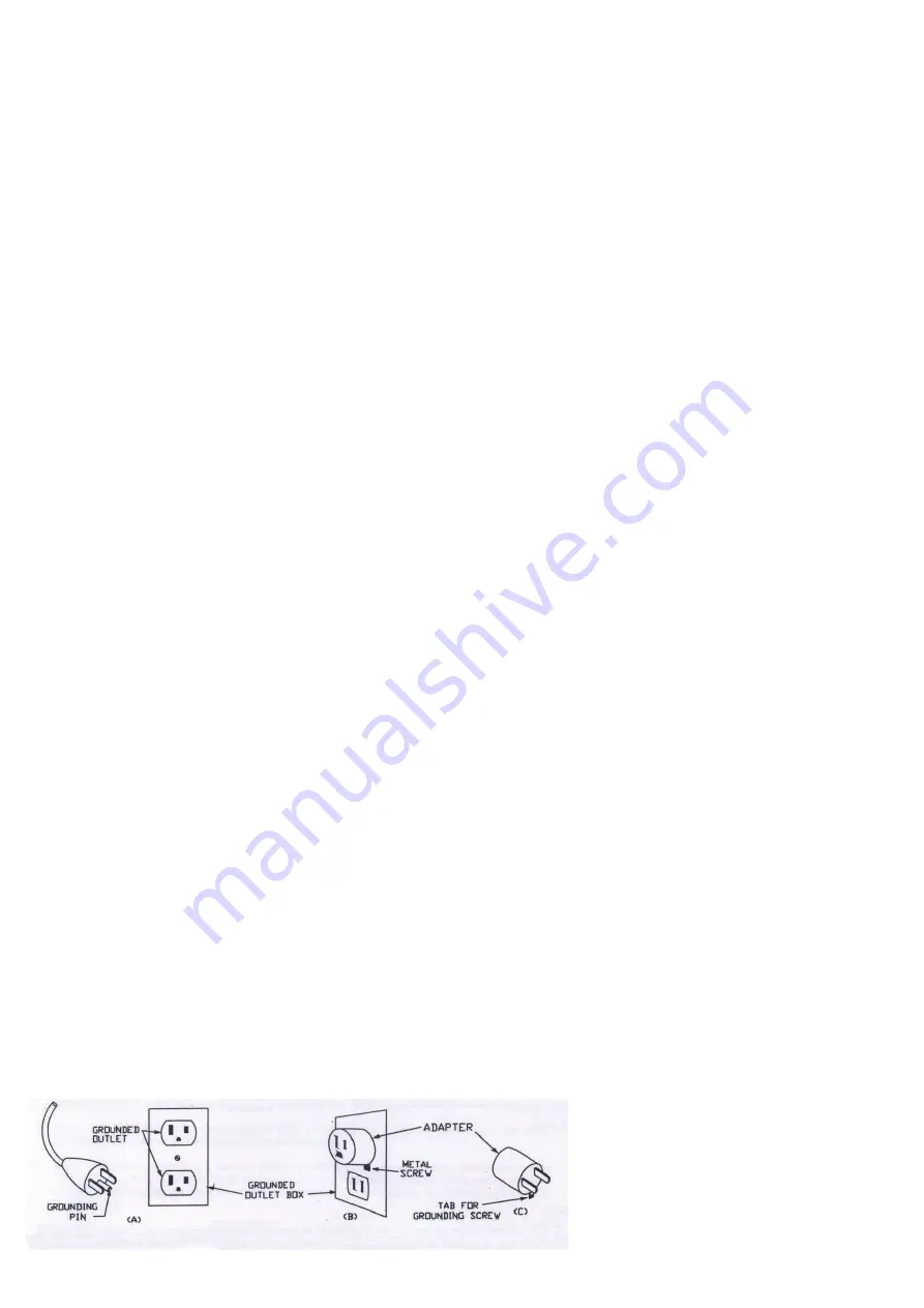
b) This product is for use on a nominal 120 or 230-V circuit, and has a grounding plug similar to the plug illustrated in sketch A
in Figure 1.1. A temporary adapter similar to the adapter illustrated in sketches B and C may be used to connect this plug to a
2 or 4-pole receptacle as shown in sketch B when a properly grounded outlet is not available. The temporary adapter shall be
used only until a properly grounded outlet (sketch A) is installed by a qualified electrician. The green colored rigid ear, lug, or si
-
milar part extending from the adapter must be connected to a permanent ground such as a properly grounded outlet box cover.
Whenever the adapter is used, it must be held in place by a metal screw. (The temporary adapter is not applicable in Canada.)
c)
Extension Cords:
Use only a 3-wire extension cord that has a 3-blade grounding plug, and a 3-slot receptacle that accepts the plug on the
product. Make sure your extension cord is not damaged. When using an extension cord, be sure to use one heavy enough to
carry the current your product draws.
For lengths less than ft, No. AWG extension cords shall be used. An undersized cord results in a drop in line voltage and
loss of power and overheating. (NOTE: Table 1.1 shows the correct size to use depending on cord length and nameplate am-
pere rating. When in doubt, use the next heavier gauge. The smaller the gauge number, the heavier
the cord.)
Figure 1.1
Grounding methods


