background image

9

IMAT AT1001U-PT1000 B - E

GB

Fig. 08

Fig. 09

Fig. 09 A

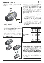
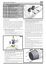
C) Pistons assembly (Part N° 40 or 40F), Fig. 10,11,12,13 
14 and 15:

•  Only for Model AT1001U R/PT1000B R and AT1001U 

FA/PT1000 B FA install screws 23, O-rings 11F, washers 
03F and nuts 04F.

•  Grease and install piston O-rings (16), the Piston skirt 

(05) and piston head (15) bearings.

•  Grease the internal surface of the body (50) and the pis-

ton (40) rack teeth.

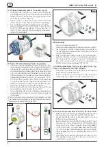
•  Hold the body (50) in a horizontal position by inserting 

the  top of the shaft into a vice or the bottom of the shaft 
connection into a male drive fitted in a vice as shown in 
figure 11.

•  Ensure that the octi-cam is in the right position as shown 

in figure 12.

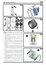
•  For standard rotation assembly (clockwise to close) ro-

tate the body (50) about 40-45° counter-clockwise from 
bottom view or clockwise from top view depending on 
which way the shaft has been linked as shown in figure 
13.

•  Press the two pistons (40) simultaneously inside the 

body (50) until the pistons are engaged and rotate the 
body clockwise from bottom view or counter clockwise 
from top view until the stroke is completed as shown in 
figure 14.

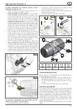
•  Ensure that with pistons completely closed, the rotation 

obtained referred to the axis of the body is about over 0° 
and that the dimension “A” on both sides is the same as 
shown in figure 15.

•  Only for Model AT1001U R/PT1000B R and AT1001U 

FA/PT1000 B FA, adjust screws 23, until the desired 
stop. 


position at 0° is achieved. Then tighten the stop adjust-
ment nuts (04F) to lock it in place.

Fig. 11 

Fig. 12

Fig. 13

40° - 45°

Fig. 10

15

16

05

Summary of Contents for AT1001U/PT1000B

Page 1: ...1U PT1000 B E ISSUE 02 18 GB INSTALLATION MAINTENANCE AND OPERATING INSTRUCTION MANUAL For AIR TORQUE ACTUATOR Model Type AT1001U PT1000 B and AT1001U R PT1000B R Double acting D and Spring return S 0...

Page 2: ...KING CONDITIONS AND TECHNICAL DATA pag 3 4 OPERATING FUNCTION AND DIRECTION OF ROTATION pag 4 5 INSTALLATION INSTRUCTIONS pag 4 6 MAINTENANCE INSTRUCTIONS pag 5 7 STORAGE INSTRUCTIONS pag 11 8 LIFTING...

Page 3: ...orated in a system or used within safety devices or circuits the customer shall ensure that the national and local safety laws and regulations are ob served In case the actuator is installed on a valv...

Page 4: ...ator must not be pressurized at any time during installation as injury may result The utmost cleanliness is required during air supply con nection to the actuator i e the connecting pipe thread fittin...

Page 5: ...uator 3 onto the valve 5 It is possible to assemble the valve onto the actuator in two ways Direct mount fit the stem of the valve 5 directly into the female connection of the actuator 3 and bolt toge...

Page 6: ...TION 01 1 OCTI CAM Stop arrangement 02 2 ANTI BLOWOUT STOP SCREW 02 1 2 SPRING CLIP Anti Blowout stop screw optional 03 2 WASHER 04 2 NUT Stop screw 05 4 BEARING Piston back 06 1 BEARING Pinion top 07...

Page 7: ...ve shaft is disassembled the stop screws may be totally removed by screwing completely into the body For model AT1001U R PT1000B R and AT1001U FA PT1000 B FA if necessary the screw plugs 02F may be re...

Page 8: ...er for spiral rings IMAT AT1001U PT1000 B E GB Fig 06 D Pistons disassembly Part N 40 or 40F Fig 04 Fixing the drive shaft 60 in a troper hub or similar de vice rotate the body 50 until the pistons 40...

Page 9: ...ndard rotation assembly clockwise to close ro tate the body 50 about 40 45 counter clockwise from bottom view or clockwise from top view depending on which way the shaft has been linked as shown in fi...

Page 10: ...ld be oriented as shown on figure 17 Fit end cap O ring seal 14 into the groove in the end cap on both end caps Fit O rings external chamber connections 09 1 on both sides Ensure that the body is perp...

Page 11: ...y open position screw or unscrew the end cap adjustment screw 221G 222G until the desired position is achieved It is important that the two end cap adjustment screws are both in contact with the pisto...

Page 12: ...11 Factory Via dei Livelli Sopra 8 24060 COSTA DI MEZZATE BG Italy Tel 39 035 682299 Fax 39 035 687791 info airtorque it www airtorque it This manual is property of AIR TORQUE S p a Costa di Mezzate...

Reviews: