


10
IMAT AT1001U-PT1000 B - E
GB
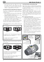
Fig. 14
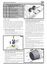
Air connection
Fig. 15
4°
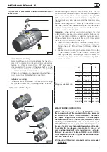
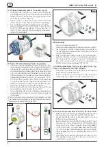
D) End cap (Part N° 30 for model AT1001U/PT1000 B,
Part N° 32 for model AT1001U R/PT1000B R) and spring
cartridge (17) assembly, Fig. 16, 17,18 and 19:
• Assemble one end cap at a time.
• Lubricate the inside surface of end caps and piston ”O”
rings 16.
• Lubricate the body.
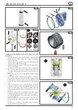
• For spring return actuators, insert the springs in each
end cap according to the desired configuration, as
shown in figure 18 and related tables (referring to the
total number of springs). Insert spring cartridge (17) as
shown in figure 17. Springs housing of pistons should be
oriented as shown on figure 17.
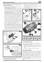
• Fit end cap O-ring seal (14) into the groove in the end
cap, on both end caps.
• Fit O-rings external chamber connections (09.1) on both
sides.
• Ensure that the body is perpendicular to the pistons,
than fit end caps onto the body (50), verifying that the
O-ring remains in the groove.
• Only for actuators with 50% or 100% stroke adjust-
ment, ensure that the adjustment screws 221G/222G
are completely screwed into the end-cap.
• Insert the cap screws (13) and the washer cap screw
(13A) and tighten each only partially. Complete tighten-
ing by making 1-2 turns for each screw in the sequence
shown in figure 19 until tightening is completed. See the
table for screw tightening torque.
Fig. 16
Fig. 17
4°
Fig. 18
Side A
Side B
Fig. 19
3
8
2
5
6
13
4
7
1
Side B
Side A
14
A
A
=
=


