


7
ONLY FOR MODEL AT1001U R /PT1000B R
and AT1001U FA /PT1000B FA
02F
2
SCREW (Plug)
03E
2
WASHER (Plug)
03F
2
WASHER (Piston Threaded)
04E
2
NUT (End Cap Threaded)
04F
4
NUT (Piston Threaded)
11E*
2
"O" RING (End Cap Threaded)
11F*
2
“O” RING (Piston Threaded)
23
2
REW (INTERNAL Stroke Adj.)
24
2
SCREW (EXTERNAL Stroke Adj.)
32
2
RIGHT AND LEFT END CAP (Threaded)
40F
2
PISTON (Threaded)
*Suggested SPARE PARTS for maintenance
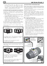
6.2) Disassembly
When disassembly of actuator is required for maintenance,
firstly remove the actuator from the valve. Before performing
any disassembly operations it is important to verify that the
actuator is not pressurised. Always use caution and double
check that the ports 2 and 4 are vented and are free from any
accessory and/or device. When the actuator is a spring return
unit, make sure that the actuator is in the failed position and
with pistons completely inwards before disassembling.
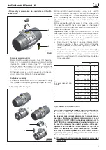
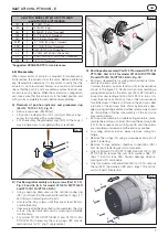
A) Removal of position indicator and graduated ring
(Part N° 19,19.0,19.1), Fig. 01:
• Remove cap screw (39) if fitted.
• Lift position indicator (19 or 19.1) off shaft, it may be nec-
essary to pry gently with a screwdriver.
• Lift, if necessary, the graduated ring (19.0) off the body, it
may be necessary to pry gently with a screwdriver.
Fig. 01
39
19
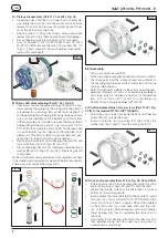
B) Positioning/disassembly of stop screws (Part N° 02),
Fig. 02 and 06 (N.A. for model AT1001U R/PT1000R
and AT1001U FA/PT1000 B FA):
• Using snap-ring pliers remove the optional spring clip
(02.1), both nuts (04) the washer (03) and the O-rings (11)
and discard if replacing all soft parts.
• Unscrew the stop screws until they are at least 80 mm
outside the body.
• If necessary after the drive shaft is disassembled, the stop
screws may be totally removed by screwing completely
into the body.
• For model AT1001U R/PT1000B R and AT1001U FA/
PT1000 B FA if necessary, the screw plugs 02F may be
removed only for “O” ring 11 replacement.
Fig. 02
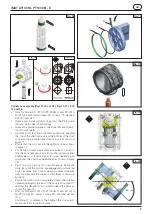
C) End Caps disassembly (Part N° 30 for model AT1001U/
PT1000B, Part N° 32 for model AT1001U R/PT1000B
R and AT1001U FA/PT1000 B FA), Fig. 03:
• End caps disassembly for spring return actuators (disas-
semble one end cap at a time).
Unscrew the end cap bolts (End cap 13) in the sequence
shown in the figure 03. Caution: when disassembling a
spring return actuator, the end caps (30 or 32) should be
loose after unscrewing end cap bolts (13) 4-5 turns. Un-
screw the ands caps bolts by a step of one turn sequence
for all the screw. If there is still force on the end caps after
4-5 turns of the end cap bolts, this may indicate a dam-
aged spring cartridge and any further disassembly should
be discontinued. Further disassembly of the end caps
may result in injury.
• End caps disassembly for double acting actuators (disas-
semble one end cap at a time). Unscrew the end cap bolts
(13) in the sequence shown in figure 03, until the screws
are completely unscrewed and the end caps are free.
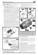
• For spring return actuators, always remove spring car-
tridge.
• Remove the o-rings (14) using a screwdriver. Discard soft
parts if replacing.
• Remove O-rings external chamber connections (09.1)
and discard if replacing all soft components.
• Only for Model AT1001U/PT1000B R and AT1001U FA/
PT1000 B FA remove the nuts 04E, washers 03E, “O”
rings 11E and screws 24E. Discard bearings when re-
placing all soft components.
• Only for actuators with adjustment 50% or 100%, remove
the nut 04R, the washers 03R and o-rings 11R and dis-
card soft parts if replacing.
Fig. 03
3
8
2
5
7
6
13
1
4
IMAT AT1001U-PT1000 B - E
GB
02


