


3
IMAT AT1001U-PT1000 B - E
GB
1) GENERAL
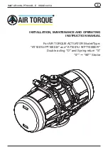
This instruction manual contains important information re-
garding the installation, operation, maintenance and storage
for AIR TORQUE rack and pinion pneumatic actuators.
Please read these instructions carefully and keep them for
future reference. It is important that the use and maintenance
of the actuator is made only by properly trained personnel.
2) WARNING
• Do not operate the actuator using inflammable, oxidizing,
corrosive, explosive or unstable gases or liquids (use only
not dangerous fluids – group 2 according to 2014/68/EU
directive). Moreover, for actuators installed in potentially
explosive zones, make sure that the internal parts of the
actuator do not come into contact with the external at-
mosphere.
• Referring to the Machinery Directive 2006/42/EC, the
actuators can be classified as “PARTLY COMPLETED
MACHINERY” (see the DECLARATION OF INCORPORA-
TION). Therefore the actuator can not put into service
until the machinery and/or the system, where the actuator
is incorporated, will be declared in compliance with the
requirements of the Directive 2006/42/EC.
• Air Torque actuators are designed, produced and
classified according to the ATEX Directive 2014/34/EU
(see actuator label and safety instructions).
The use of the actuators in potential explosive atmos-
phere zones has to comply with the ATEX classification
indicated on the actuator label and according to the ATEX
safety instructions.
• The use, the installation and the maintenance of the Air
Torque actuators must be made by adequately trained
personnel. For the use, installation and maintenance of
Air Torque actuators it is recommended to comply to the
safety notice and to use proper equipment to protect
health and prevent accidents.
• It is important that the actuator is used only within the
working limits indicated in the technical specifications.
• Do not operate the actuator over temperature limits: this
could damage internal and external components (disas-
sembly of spring return actuator may become dangerous).
• Do not operate the actuator over pressure limits: this
could damage internal parts as well as cause damage to
the housing and end-caps.
• Do not use the actuator in corrosive environments with
incorrect protection: this could damage the internal and
external parts.
• Do not disassemble individual spring cartridges, this
may result in personal injury. If maintenance to springs is
necessary, send them to AIR TORQUE.
• Close and disconnect all air supply lines and make sure
that air connections are vented during maintenance and
installation on valve.
• Do not disassemble the actuator or remove end caps
while the actuator is pressurized.
• The 4th GENERATION Upgrade Series actuators are
designed to be used only on valves.
• Before installing the actuator onto the valve make sure
that the rotation direction and the position indicator are in
the correct position.
• If the actuator is incorporated in a system or used within
safety devices or circuits, the customer shall ensure that
the national and local safety laws and regulations are ob-
served.
• In case the actuator is installed on a valve with a
gearbox for emergency manual operation, make sure that
the stroke of the gearbox does not exceed the stroke al-
lowed by the actuator. Caution: make sure that the gearbox
stroke, both in closed and in opened position, is properly
adjusted. If you exceed the stroke allowed by the actua-
tor with the manual operation of the gearbox, you can
cause severe damage to the adjustment screws, to the
pistons and to the actuator itself.
3) WORKING CONDITIONS AND TECHNICAL DATA
• Operating media:
Dry or lubricated air or inert gases, provided that they are
compatible with the actuator internal parts and lubricant. The
operating media must have a dew point equal to –20°C (-4°F)
or at least 10°C below the ambient temperature. The maxi-
mum particle size contained into the operating media must
not exceed 30 μm.
• Supply pressure:
The maximum supply pressure is 8 bar (116 Psi) only for
AT1001U/PT1000 B
spring return type and
AT1001U R/
PT1000B R
double acting and spring return. While for type
AT1001U/PT1000 B
double acting the maximum supply
pressure is 7 bar (101,5 Psi).
• Operating Temperature:
⇒
“Standard”
actuators from -40°C (-40°F) to +80°C (+176°F)
⇒
Actuators for high temperature
“HT”
from -15°C (+5°F) to
+150°C (+300°F)
⇒
Actuators for extreme low temperature
“LLT”
from -55°C
(-67°F) to + 80°C (+176°F)
Caution: for low and high temperature service, special grease
and special components are required. Please contact AIR
TORQUE. Working at high or low temperature can affect the
life and the output torque of the actuator.
• Operating Time (see Technical Data Sheet):
Caution: the operating time depends on several factors such
as supply pressure, supply system capacity (pipe diameter,
flow capacity of pneumatic accessories), valve type, valve
torque and figures, applied safety factor, cycle frequency, tem-
perature, etc.
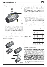
• Rotation and stroke adjustment (see technical data sheet):
For standard actuator 90° rotation.
Stroke adjustment at 0° (closed pistons): +5° / – 5°. Stroke
adjustment at 90° (open pistons): +5° / – 5°.
• Lubrication:
The actuators are factory lubricated for the life of the actua-
tor in normal working conditions. The standard lubricant type
GSTD is suitable for use from -40°C (-40°F) to +80°C (+176°F).
For extreme low temperature (LLT) and high temperature (HT)
service, special grease is required: please contact Air Torque.
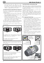
• Construction:
Rack and pinion actuator design suitable for both indoor or
outdoor installations.
• Protection and Corrosion resistance:
All the actuators are supplied with corrosion protection for
normal environments. For corrosion resistance of the different
types of protection see technical data sheet. Before installing
the actuator in aggressive environment, ensure that the se-
lected protection level is suitable.
• Actuator designation and marking (see technical data
sheets):
The actuator type, size, operating pressure, output torque,
direction of rotation, spring action, operating temperature
and type of connections/interfaces are determined by des-
ignation.


