Air Techniques AirStar AS120 Installation & Operating Instructions Manual Download Page 11

Page 11

Air Techniques, Inc. 

While the compressor aggregate is in operation the accumu-
lating condensate is separated by being conveyed through 
the cyclone separator and, in a second step, through a 
refrigerant dryer and then separated to the waste water 
system� This process is carried out automatically using a 
valve in the cyclone separator and the refrigerant dryer 
controller, depending on the level present�

A special load controller monitors the compressor aggregate 
operation and implements an alternation of compressor 
operation on a rolling system� The alternation is carried 
out according to the number of operating hours each 
individual compressor aggregate has performed�

The pressure in the tank can be read off using a pressure 
gauge and also at the display panel�

Auxiliary operation
Depending on the amount of compressed air required and 
the particular set up of the compressed air network it may 
be necessary for two (or more) compressed air stations 
to work together on one network� In this particular set up 
one compressed air station operates in main operation, 
the other(s) in auxiliary operation� 
The settings for auxiliary operation are carried out on 
initial set up and configuration of the complete unit using 
the display panel� In auxiliary operation the control range 
for cutting in and cutting off pressure for the compressed 
air station is lowered by 1�5 psi (0�1 bar)� In this way the 
compressed air station aggregates switch in main and 
auxiliary operation alternately on and off�

5�3  Emergency mode

Emergency mode can only be used for short periods in 
order to maintain an emergency supply of compressed 
air in the cases of a possible defect in the system�
Turning the switch (4) to the Emergency mode setting "1" 
switches on the first compressor aggregate and it starts 
up in pressure free state� 
After approximately 3 seconds the switch (4) can be rotated to 
position "2"� The solenoid valve opens the pressure line and 
the compressor aggregate begins to supply the pressure tank� 
The compressor aggregate then runs in continuous operation� 
The alternation of aggregates no longer takes place� 
When no air is taken from the tank, the pressure in the tank 
increases to 145 psi (10 bar) and will be maintained at this 
level by the opening of the safety valve� The safety valve 
produces a loud venting noise when it is in the open position�

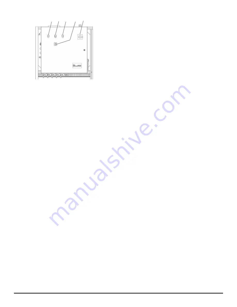
Fig� 5:  Control unit

1  Red LED "Fault"
2  Blue button "Reset"
3  Green LED “Run”
4  Emergency mode switch
5  Main power switch

5�1  Start operation

After switching on at the main power switch of the control 
unit the refrigerant type dryer is switched on and cools 
the heat exchanger to its normal operating temperature� 
Depending on the actual ambient temperature this cooling 
can take up to 3 minutes (see the temperature display on the 
refrigerant dryer)� After approx� 60 seconds the controller 
switches on the first compressor aggregate� At about 3 
seconds the next compressor aggregate will be switched 
on� A sensor monitors the pressure inside the tank, which 
is shown by the display�  Upon reaching the set pressure in 
the controller (see section Technical Data) the aggregates 
will be turned off sequentially�

5�2  Normal operation

A sensor monitors the pressure in the tank vessel� When 
compressed air is taken from the pressure tank, the pressure 
within the tank falls� At 109 psi (7�5 bar) the first compressor 
aggregate switches on� If the pressure within the tank continues 
to fall, then further compressor aggregate are switched on 
consecutively according to the switch-on pressures set (see 
4 Technical data)�
Each compressor aggregate starts up in a pressure free 
state� After approximately 3 seconds the solenoid relief 
valve opens the pressure line and the aggregate begins 
to supply the pressure tank�
When the pressure within the tank rises, the compressor 
aggregates are switched off one after the other as soon 
as the preset cut off pressure of 116 psi (8 bar) has been 
reached (see 4 Technical data)�

When more compressed air is taken from the tank the pressure 
falls and the next aggregate switches on automatically� When 
the tank pressure falls below 15 psi (1 bar), the compressed 
air station switches over to emergency mode (one compressor 
aggregate remains in continuous operation)�

1

3

2

5

4

Summary of Contents for AirStar AS120

Page 1: ...Installation Operating Instructions AirStar Clinical Air Compressor AS60 AS90 AS120 AS60 400 AS90 400 and AS120 400...

Page 2: ......

Page 3: ...8 2 Module layout 12 8 3 Set up and secure modules 12 9 Installation 13 9 1 Connect the compressed air connection to the cyclone separator 13 9 2 Connect the pressure tank to the com pressed air supp...

Page 4: ...jury IMPORTANT Possible danger which could result in serious damage Further symbols The following symbols are used within this document and on the actual appliance Notes e g special instructions conce...

Page 5: ...xperience Every person operating the device must be trained in its handling Installation and repair and maintenance Installation resetting alterations adding of extensions and repairs must be carried...

Page 6: ...nd Operating Instructions AS60 400 Control module Compressor module with 2 compressor aggregates Boost transformer Connecting cables and hoses Mounting materials Installation and Operating Instruction...

Page 7: ...ule control module lbs kg lbs kg 505 229 700 318 835 379 700 318 1055 479 700 318 Shipping Weight compressor module control module lbs kg lbs kg 605 275 850 386 940 425 850 386 11505 522 850 386 Conne...

Page 8: ...ame of manufacturer Air Techniques Name of unit AirStar Clinical Air Compressor Models AS60 AS90 AS120 AS60 400 AS90 400 AS120 400 Control panel ConformstoUL508A theULStandardforConstruction Of Indust...

Page 9: ...d air which is used to operate dental units simulation stations phantom places and similar The display panel is used to configure the operation of the device monitor the operating status e g fault rep...

Page 10: ...ar 7 Control connection 8 Tank connection to air network 1 inch NPT 9 Condensate drain 10 Condensate separator drainage 11 Pressure sensor 12 Refrigerant dryer bypass valve 13 Refrigerant dryer valve...

Page 11: ...ggregatethenrunsincontinuousoperation The alternation of aggregates no longer takes place When no air is taken from the tank the pressure in the tank increases to 145 psi 10 bar and will be maintained...

Page 12: ...ation in purpose built rooms e g boiler room must be checked against building regulations beforehand Do not operate the units in damp or wet environments Clearly indicate that the room may only be ent...

Page 13: ...air supply net Connect the pressure tank to the supply network using a flexible compressed air hose on site connection 1 inch NPT external thread 9 3 Connect the condensate drain outlet to the waste w...

Page 14: ...e following information on connecting electrical lines is based on US and Canada standards Always observe the relevant national standards and local rules and regulations Diameter of the connections Th...

Page 15: ...ave been used The compressed air for the dew point measurement should be taken from the measuring connection point 1 1 11 Initial start up Wear ear protectors 11 1 Switching on compressed air station...

Page 16: ...e switch to Emergency Mode setting 2 The compressor aggregate then runs in continuous operation The red LED Fault shows 0 1 2 13 Decoupling a single compressor aggregate Where a single compressor aggr...

Page 17: ...tighten screws Check the compressed air connections for any signs of leakages if necessary seal Check the operating hours of the compressor aggregates If there are large differences in the compressor...

Page 18: ...n relief valve Change the controller at the display panel to manual Switch on the individual compressors aggregate manu ally using the display panel After approximately 5 seconds the non return relief...

Page 19: ...eak Check units and air supply for signs of leakages if necessary seal leaks Display Pressure sensor 1 defect Units do not function red LED Fault lit Connection between pressure sensor and controller...

Page 20: ...sary replace module 16 2 Further messages at display panel The following messages give information but do not indicate a fault or downtime of the units Message Probable cause Solution Bacterial filter...

Page 21: ...safety of the system according to current national and local code has been checked and confirmed Training in the operation and handling of the unit s has been carried out See back page The delivery r...

Page 22: ...Inc Page 22 Trained Personnel Log Name Signature Date Name Signature Date Name Signature Date Name Signature Date Name Signature Date Name Signature Date Name Signature Date Name Signature Date Form i...

Page 23: ...it will not be applied to product returns that exhibit damage due to shipping misuse careless handling or repairs by unauthorized personnel Credit or partial credit will not be issued until products p...

Page 24: ...er Evacuation System Cleaner Imaging Accessories Chemistry Processor Accessories For over 50 years Air Techniques has been a leading innovator and manufacturer of dental products Our priority is ensur...

Reviews: