background image

- 13 -

UG-MD16E-EN (V1.3-190708)

MD-16E

Mixer Reference manual

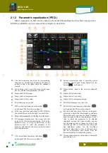
2.1.2 Parametric equalization ( PEQ )

MD-16 equipped every MIC/Line In channel with 4 bands PEQ and High/Low Pass filter, Among which

BAND1 and BAND4 can select normal filter or High/Low shelf Filter

01

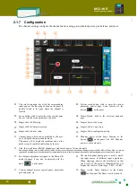
The total navigation bar, click the corresponding

index page or the fader page button on the panel to

quickly switch to the page where the channel is

located.

02

System setup button, click to enter the system

parameter control page. Same function as the
button

on the panel.

03

Scene button, click to enter the scene control page.

Save or load the scene parameters you need.

04

Home Button, back to the overview channels

page.

05

Single click to PEQ setup.

06

Single click to Gate setup.

07

Single click to Compressor setup.

08

Single click to Copy setup.

09

Single click to Preset setup.

10

Single click to configuration setup.

11

PEQ filter gain scale in dB.

12

PEQ filter frequency scale, unit: Hz.

13

HPF switch. Same function as the button
on the panel. The filter is active when lit.

14

PEQ switch. Same function as the button
on the panel. The PEQ is active when lit.

15

Filter type selection, and when BAND1 BAND4,

the normal filter or select the high / low shelf filter.

16

EQ curve and filter point, click on a color point,

press drag to adjust the filter frequency and gain.

The dotted circle represents the current frequency

band, the right list shows the parameters, click or

slide to select the parameter to be adjusted

(displayed as green text when selected), you can

use the main jog dial to change the value. Press

the main jog dial to switch between coarse and

fine adjustment modes. Use the two-finger

gesture to adjust the Q value. In the main unit,

use two semi-circular color blocks. Press the

horizontal push-pull to adjust the Q value.

17 Reset all parameters of the EQ to a flat state.
18

EQ parameter display area, the current text edit

point will be filtered enlarged display. Click on the

parameter area or swipe up and down in the

parameter area to select the parameter to be

adjusted, and then use the main jog dial to make

precise adjustments.

19

LPF switch. Same function as the button
on the panel. The filter is active when lit.

20

Current channel master control panel, adjustable

gain and mute, etc.

03

02

01

04

06

07

08

09

10

20

05

13

14

15

17

19

11

12

18

16

Summary of Contents for MD-16E

Page 1: ...AIMIX DIGITAL LIVE SOUND CONSOLE Reference manual Digital mixer Applicable to Firmware Version 1 3 MD 16E ...

Page 2: ...UG MD16E EN V1 3 190708 MD 16E Mixer Reference manual ...

Page 3: ...MD16E EN V1 3 190708 MD 16E Mixer Reference manual Before installation operation and maintenance of this product please make sure to firstly read the Important Safety Information on page III of this Manual ...

Page 4: ... I UG MD16E EN V1 3 190708 MD 16E Mixer Reference manual Revision history Revision Revision description and content updated V1 0 Initial version V1 3 Official version ...

Page 5: ...ese instructions may result in equipment damage and this damage is not within the range of quality guarantee Attention is the term used to indicate other useful information Important Information is a term denoting a vital explanation or information for successful completion of one step The purpose of the excalmatory mark in an equilateral triangle is to remind the user of paying attention to the i...

Page 6: ...with the sign of corrosion or overheat nor any power cord that it seems damaged in any way as the damaged power cord may cause a fire or an electric shock Make sure to use the power supply outlet and power cord with protective grounding so as to maintain the equipment in good protective grounding During system installation do not connect it to the network power supply but make the connection only ...

Page 7: ... generated in special installation conditions If the machine indeed brings harmful interference to radio or television reception can be determined by turn on or turn off the machine users are encouraged to try one or more of the following measures to rectify this interference Change the orientation of the receiving antenna or resetting Increase the distance between the equipment and the receiver S...

Page 8: ...D 16E Mixer Reference manual Packing content of MD 16E Mixer MD 16E Main Unit Not including tablet 1pcs AC power cord 1pcs WIFI wireless adapter USB interface 1pcs Bluetooth adapter USB interface 1pcs User s reference manual 1pcs ...

Page 9: ... 1 6 Monitor headphone 10 1 7 Restrictions on USB interface power 10 Chapter 2 Detailed Description of MD 16E 11 2 1 Input Channels 12 2 1 1 Overview of input channels 12 2 1 2 Parametric equalization PEQ 13 2 1 3 Gate 14 2 1 4 Compressor 15 2 1 5 Copy to 16 2 1 6 Preset 17 2 1 7 Configuration 18 2 2 Output Channels 19 2 2 1 Overview of output channels 19 2 2 2 PEQ Same as the input channel please...

Page 10: ...5 2 5 2 USB recording 36 2 5 3 Bluetooth playback 37 2 6 Grouping shortcuts 38 2 6 1 DCA volume grouping 38 2 6 2 Mute Groups 40 2 7 SCENES 41 2 8 System settings 42 2 8 1 Automix this feature is not available yet 43 2 8 2 Signal Generator 44 2 8 3 Firmware Upgrade 45 2 8 4 Network settings and iPad remote operation 45 2 9 Power standby and recovery 46 2 10 Programmable central control remote oper...

Page 11: ...nction can easily save or recall optimized parameter configurations From now on you can experience the professional tuning fun easily and contentedly Scan to follow WeChat public number Download the latest available firmware version of MD 16E install The latest functions for your mixer or optimize and upgrade the performance Timely receive the latest update notice Obtain the relevant member favora...

Page 12: ...low shelf filter LSF high pass filter HPF low pass filter LPF Configuration 2 professional DSP effectors FX 6 effect types Chorus Echo Flanger Pitch Shift Reverb ping pong Stereo Delay totally over one hundred types of effect preset Use the functions such as wizards message indicators and Scenes Presets Copy to help users easily complete channel configuration gain settings and effect selection Use...

Page 13: ...programs ensuring that the MD 16E digital mixer you purchased will be readily and completely upgraded to the latest state MD 16E mixer provides Wireless WiFi hot spot the IOS device Apple iPad etc can be wirelessly connected to the mixer for remote controlled operation The APP software can conduct wirelessly remote control operation of nearly all the parameters of the mixer The mixer is self provi...

Page 14: ...MID and HI buttons simultaneously to switch to DCA operation page layout 04 Fader page switch button for bus output channels 05 Fader page switch button for input channels or routing 06 Motorized faders 07 Multi color guidance screen instantly plays the associated channel information 08 Channel MUTE or Routing MUTE 09 Solo monitor buttons 10 Channel select button single push will enter the setup o...

Page 15: ... detect the interval of 2 TAPs and will make it as delay of the effect the indicator under the push button will keep the same time as delay effect time 23 MENU setup 24 AUX SUB output BUSES Routing setup 25 MUTE group quick butoon double click to switch 27 USB dock can connect WIFI adapter BT adapter and USB stick note BT and USB can t work at same time 28 USB quick button single click will enter ...

Page 16: ...interface 05 Bus SUB1 SUB4 output Mono differential balanced output XLR male interface 06 Bus Main L R output Mono differential balanced output XLR male interface 07 Internet connection can work with IP currently not open 08 Headphone monitor output interface 09 USB dock can connect WIFI adapter BT adapter and USB stick NOTE BT and USB can t work at same time 10 Foot switch input interface Current...

Page 17: ... function to paste the specifications to other channels rapidly 5 Single click Back to return to overview of channels put the volume fader to right level normally it s 0dB single click MUTE button to cancel the channel MUTE 6 Under Default mode the input channel signal will go through Main L R as output you can adjust the volume to right level and MUTE off then you can hear the sound 7 If you choo...

Page 18: ...Or single click the fader page button to switch to the effect interface single click SEL can also enter the setup for effect And follow step 7 8 send the effect to the related output BUS the output channel will work with the effect 11 Congratulations the quick tuning operation is successful You can learn and master the MD 16E digital mixer in the following chapters to experience the joy of tuning ...

Page 19: ...all After recalling you can modify the specs per your request In the scene there is a default scene if you choose this all setup will be cleared and return to factory default NOTE You can also reset the machine or restore the factory settings as needed in the Setup menu 1 5 Use Presets to tune What is the preset The channel preset is a group of multi parameter settings saved and aimed at one chann...

Page 20: ...or the mixer it will produce interference Use the phone comes with the charger from other places to take power and the phone as the input source of the mixer will not be a problem 01 Rotate the headphone monitor knob on the panel to automatically pop up this monitor control interface If there is no operation it will automatically retreat in 3 seconds 02 Headphone monitoring can be accessed by clic...

Page 21: ...an be distinguished by the corresponding OLED guidance display Channels that are prohibited from operating display a black screen Status input channels Gain Inf 10dB Channel name user define Input level pre fader Channel No CH01 CH12 Channel link Input ch CH01 CH12 etc Gain Inf 10dB Channel name user define Input level pre fader BUS No AUX1 SUB4 etc Input channel Routing channel DCA gain Inf 10dB ...

Page 22: ...reen to select the channel and adjust the knob on the panel 06 Channel MUTE Grey for off red for on 07 Channel Gain Change with fader unit dB 08 Phantom power the indicator will show in working 09 Indicator of Gate it will light up when in working 10 Compressor indicator will light up in working 11 Gain level of fader unit dB 12 Signal level pre fader unit dBfs 20dBfs as standard level U 13 Channe...

Page 23: ...tion as the button on the panel The PEQ is active when lit 15 Filter type selection and when BAND1 BAND4 the normal filter or select the high low shelf filter 16 EQ curve and filter point click on a color point press drag to adjust the filter frequency and gain The dotted circle represents the current frequency band the right list shows the parameters click or slide to select the parameter to be a...

Page 24: ...k to Copy setup 09 Single click to Preset setup 10 Single click to configuration setup 11 Threshold the starting point at which the threshold is set to cause the signal level to begin to decay in dB The shortcut knob on the panel can also be adjusted 12 Reset the parameters to their initial values 13 Set the minimum time for the gate to hold the state of ON after having enabled it and the gate wil...

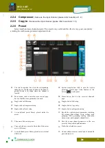
Page 25: ...ingle click to Preset setup 10 Single click to configuration setup 11 Threshold the starting point for setting the Comp to start decaying the signal level in dB The shortcut knob on the panel can also be adjusted 12 Reset the parameters to their initial values 13 Compressor switch Same function as the button on the panel The Comp is active when lit 14 Gate graphic when it s on it will turn yellow ...

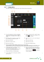
Page 26: ...rol page Save or load the scene parameters you need 04 Home Button back to the overview channels page 05 Single click to PEQ setup 06 Single click to Gate setup 07 Single click to Compressor setup 08 Single click to Copy setup 09 Single click to Preset setup 10 Single click to configuration setup 11 The white area is the current channel and the parameters are set The blue area is the target channe...

Page 27: ...l page Same function as the button on the panel 03 Scene button click to enter the scene control page Save or load the scene parameters you need 04 Home Button back to the overview channels page 05 Single click to PEQ setup 06 Single click to Gate setup 07 Single click to Compressor setup 08 Single click to Copy setup 09 Single click to Preset setup 10 Single click to configuration setup 11 Built ...

Page 28: ...displayed synchronously on the guide screen for quick identification by the user 12 Phantom power switch Same function as the button on the panel The 48V Phantom power is active when lit 13 Link the two adjacent MONO channels are linked into a pair of stereo channels Only channel linking such as CH01 CH02 CH03 CH04 etc are supported and channel linkings such as CH02 CH03 CH04 CH05 etc are not supp...

Page 29: ...he logo lights 05 Channel mute switch muted when lit 06 Channel gain Changed by fader adjustment unit dB 07 The compressor icon lights up to indicate that the compressor is enabled 08 Fader gain scale in dB 09 Signal level meter unit dBfs make 20dBfs as standard level U 10 Channel gain fader 11 Solo On Off 12 Channel name bar including the physical channel number AUX01 AUX02 etc as well as the use...

Page 30: ...e click to PEQ setup 06 Single click to GEQ setup 07 Single click to Compressor setup 08 Single click to Copy setup 09 Single click to Preset setup 10 Single click to configuration setup 11 EQ curve 12 Current gain of the filter in dB 13 The gain adjustment slider pushes to change the filter gain double click the blank area of the frequency point to reset the filter gain to 0dB You can also click ...

Page 31: ...arameters you need 04 Home button back to the overview channels page 05 Single click to PEQ setup 06 Single click to GEQ setup 07 Single click to Compressor setup 08 Single click to Copy setup 09 Single click to Preset setup 10 Single click to configuration setup 11 A user defined preset library placed inside the mixer 12 Recalls the selected preset parameters including EQ settings filter settings...

Page 32: ... Single click to configuration setup 12 Link the two adjacent MONO channels are linked into a pair of stereo channels Only channel linking such as AUX1 AUX2 SUB3 SUB4 etc are supported and channel linkings such as AUX2 AUX3 SUB2 SUB3 etc are not supported The parameters of the odd channel are automatically copied to the even channel when linked and the phantom power control is also copied 11 Chann...

Page 33: ...channel is located 02 System setup button click to enter the system parameter control page Same function as the button on the panel 03 Scene button click to enter the scene control page Save or load the scene parameters you need 04 Home button back to the overview channels page 05 Single click to PEQ setup 06 Single click to GEQ setup 07 Single click to Compressor setup 08 Single click to Preset s...

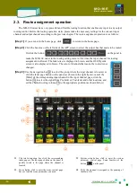
Page 34: ...the OLED guide screen is also displayed in brown The color of channels that cannot be routed is not changed Step 3 Use the navigation bar 01 to select the group where the input channel is located or click the fader page button on the panel as shown in the right figure cancel the Mute of the corresponding input channel in the input channel page click the button 10 to select the signal from Pre fade...

Page 35: ...ocessing and is controlled by the input channel volume and DCA then the access point is selected as Pst fdr after the fader The above is just an example Each output bus can individually select different access points for the same input channel 05 Routing channel mute switch When the red light is on the input channel route is muted and no signal is coupled to the bus 06 The route allocates the gain...

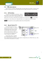
Page 36: ...et the Delay Time parameter value and the system automatically measures two neighboring time you hit the button NOTE This operation can also be performed without the FX settings interface 2 4 2 Signal Chain of FX The data link graph is shown in the right graph FX1 and FX2 have completely independent effect input buses can select any input signal source or mixing signal source for effect module The...

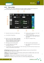
Page 37: ...id routing channel 02 System parameter button Click to enter the system parameter control page Same function as the button on the panel 03 Scene button click to enter the scene control page 04 Mute switch The FX channel route is muted when red is lit and no signal is coupled to the bus 05 Routing channel gain Unit dB Change by fader adjustment 06 Fader gain scale unit dB 07 Route Gain Fader the fa...

Page 38: ... page 02 Switch to the PEQ control page Set the high low shelf filter for the effect 03 Switch to the FX setting interface 04 Switch to the channel parameter copy pages you can copy parameters of current channel to another channel effect 05 Switch to the FX preset parameter management page you can retrieve the pre saved effect parameters eliminating the trouble of setting you can also save the adj...

Page 39: ...effect is used to create a sense of space and presence Delay Delay unit ms Input signal and feedback signal of delay Feedback The amount of feedback The output signal is fed back to the input and the number of echoes can be changed by changing the amount of feedback Scaler Echo gain ...

Page 40: ...o etc Frequency Modulation frequency Quick modulation frequency can cause one vibrato effect but frequency shift will be caused if it is too fast Depth Modulation depth Change the pitch of delay signal through the modulation of delay time 0 means no modulation 1 means max modulation Feedback The feedback of output delay signal to the input end Delay Basic delay unit ms ...

Page 41: ...easing or decreasing an audio signal tone at regular intervals WetDryMix Wet and dry mixing Input signal and delay signal mixing 0 only input signal 1 only tone effect signal Shift Positive value means the pitch has got higher and negative value means the pitch has got lower 0 original pitch Feedback The feedback of output delay signal to the input end Delay Basic delay unit ms RandDelay Random de...

Page 42: ...e interval between the front reflection and the direct sound The bigger the PreDelay the bigger the space on the contrary shorter DecayTime That s the total length of the whole reverb Different environments produce different lengths The bigger the space the bigger the decay time on the contrary smaller Depth Reverb depth Feedback strength of post reverb sound DirectSound Direct sound ratio ReverbS...

Page 43: ...nd sent out from the left and right channels through the different decay of the left and right channels like ping pong s motion trail effect Delay Create an effect of a sound that moves back and forth The sound is bigger the effect is more obvious Feedback The amount of feedback Delayed output signal is fed to the input magnitude ...

Page 44: ...back to the overview channels page 02 Single click to PEQ setup 03 Switch to the FX setting interface 04 Single click to Copy setup 05 Single click to Preset setup 06 Single click to configuration setup 07 Call the selected preset parameters to the effect module 08 Factory designed effects preset library 09 A user defined preset library placed inside the machine 10 A user defined preset library pl...

Page 45: ...ntrol interface 06 Switch to the bluetooth playback control interface 07 Single click to Preset setup 08 Single click to configuration setup 09 Play progress and time indication Push and pull the progress bar fader slider to fast forward or rewind 10 Music file directory specification If the music file is not stored in the root directory of the USB disk you need to click this button to specify the...

Page 46: ...2 Home button back to the overview channels page 03 Single click to PEQ setup 04 Switch to the USB playback control interface 05 Switch to the USB recording control interface 06 Switch to the bluetooth playback control interface 07 Single click to Preset setup 08 Single click to configuration setup 09 The recording file format is selected and can be saved in WAV or FLAC lossless format 10 Record b...

Page 47: ...ts the system does not allow USB disk and Bluetooth to play at the same time 01 Click the FX USB AES group on the navigation bar switch to the USB overview page and then click the USB channel name bar to enter the USB control interface As shown above 02 Home button back to the overview channels page 03 Single click to PEQ setup 04 Switch to the USB playback control interface 05 Switch to the USB r...

Page 48: ...ess the button on the panel at the same time to quickly switch to the DCA overview page as shown below Operate the button of 02 or click the button on the panel to achieve one key group mute The fader or motorized fader of operation 03 can realize a fader to control a group of volume 01 Click the DCA group on the navigation bar to switch to the DCA Overview page As shown above 02 When Mute is lit ...

Page 49: ... the DCA settings interface as shown below 01 DCA number 02 DCA channel name 03 DCA mute switch red light indicates mute all channels associated in advance will be muted by one button 04 Associated input and output channels color indicates that they are already associated click to switch 05 Return to the DCA overview screen 06 DCA volume grouping Pushing the fader controls all pre associated chann...

Page 50: ...sponding mute group When the yellow light is on the mute group is active and the associated input output channel will be muted In the system parameter interface you can set the mute group as follows 01 Back to the overview channels page 02 Mute Groups channel number 03 Mute Groups channel name long press this button to rename 04 Mute Groups mute switch yellow light indicates mute all channels pre ...

Page 51: ...a number of pre set scenes for a variety of performances For the show you are going to tune you can find the one that works best for you Use the scene presets to quickly configure the device to the desired working state Click on the screen to enter the scene operation interface call the scene parameters you need and restore the machine to the working state you need with one click 01 Back to the ov...

Page 52: ...tor settings interface 05 Click to enter the system upgrade interface 06 Click to enter the permission control management interface 07 Click to clear all mute settings including channel mute and mute grouping Click DCA to clear the DCA s mute setting and set the DCA volume to 0dB Click to clear all SOLO settings 08 Reset all input channels to their initial state Reset all output buses to their ini...

Page 53: ...tic mixing channel and the channel that does not participate in the automatic mixing 05 Select the output bus for the automix feature 04 Auto mix on off 07 Input channel label 06 The bus name of the current automix 09 The weight of the channel is assigned The weight range is 0 100 and 100 is the maximum weight The system counts the weights of all channels participating in the auto mix and assigns ...

Page 54: ...or commissioning calibration and external devices for the mixer 01 Return to the home page 02 Set the frequency of the sine wave from 20Hz to 20kHz 03 Select the signal type sine wave white noise pink noise 04 Signal wave forms are sine wave white noise pink noise 05 The associated output buses when highlighted indicates that the signal is coupled to the bus Click to switch 06 Signal generator swi...

Page 55: ...al operating conditions 3 Enter the system settings interface Click Upgrade on the screen Start the firmware upgrade program ISUeasy TM Read the precautions carefully and confirm that it is correct Click Continue to perform the upgrade process The upgrade process takes a few minutes please be patient Do not power off during this process to avoid the upgrade failure and equipment failure 2 8 4 Netw...

Page 56: ...hotspot name in the Name field enter the connection password in the Password field and then click the button Reboot WIFI to make the settings The parameters take effect See section 2 8 4 for details 3 Turn on the iPad Click the settings button Click the WIFI button Turn on WIFI and select the network set on MD 16E 4 Log in to the Apple App Store with your iPad find the app with the keyword MD 16E ...

Page 57: ...xer recovery Normal working condition The power light is always on 2 10 Programmable central control remote operation Using the device s network port or WIFI hotspot this digital mixer can accept remote control commands from the center console Through the centralized control of the programmable central control unit you can quickly and efficiently control the main parameters of the MD 16E digital m...

Page 58: ... 48 UG MD16E EN V1 3 190708 MD 16E Mixer Reference manual ...

Page 59: ...ffect processing 60 factory presets FX Presets simple and easy presets for users Presets Presets of mixer User presets include saving or recalling all mixer parameters from the internal and U disk to mixer Channel presets User channel presets can be saved or recalled from the internal and U disk to mixer Scene mode You can implement Save Delete Recall Export Import of the scene External control Ap...

Page 60: ...e RMS i e uVrms mVrms and Vrms C Analog output characteristics Output port Used for standards Output impedance Output level 1 Port Rated Maximum distortion before the level AUX1 AUX2 600Ω line 75Ω 4dBu 1 23V 23dBu 11V 1 4 TRS Balance SUB1 SUB4 Main L R 600Ω line 75Ω 4dBu 1 23V 23dBu 11V XLR 3 32 balanced Phones 32Ω Phone 51Ω 0 82Vrms 21mW 2 1 83Vrms 105mW 1 4 TRS Stereo Unbalanced 300Ω Phone 51Ω 1...

Page 61: ... 51 UG MD16E EN V1 3 190708 MD 16E Mixer Reference manual Appendix 2 The Mixer Block Diagram ...

Page 62: ... 52 UG MD16E EN V1 3 190708 MD 16E Mixer Reference manual Appendix 3 Dimensions 460mm 435mm 138mm 76mm ...

Page 63: ... 53 UG MD16E EN V1 3 190708 MD 16E Mixer Reference manual ...

Page 64: ...AIMIX TM AIMIX Audio System Equipment Co Ltd TEL 020 87507568 020 85510215 WebSite www ai mix com E Mail support ai mix com MD 16E Showing rich sound connotations MIX ...

Reviews: