Page 11
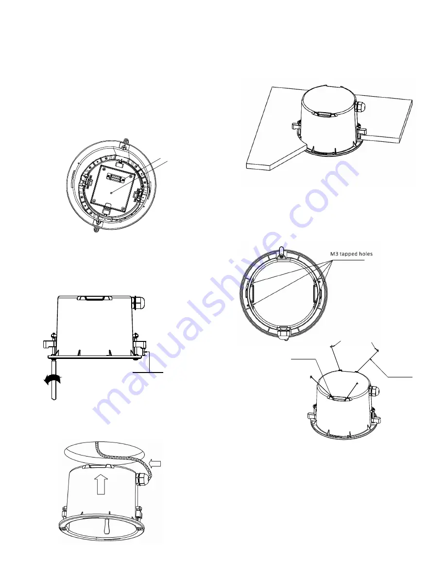
Figure 28 – Check LED
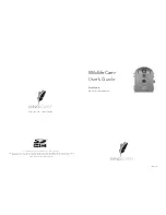
Figure 31 – Extend ceiling clips
AMP Socket
LED
Figure 30 – Raise unit into ceiling
Figure 32 – Support Wire Holes
and Attachment Locations
Attach to housing
usi ng M3 Screws
Attach to support beam
Support wires
Before closing the access panel, set the dip switches (see
Figure 16) to select the desired Camera ID, Protocol, and Baud
rate. Refer to the appendix of the Operation Manual for dip
switch information.
Pull excess wire back through the bulkhead connector so that
the access panel can close properly. Tighten down the
tightening cap once the wires are in the desired position.
Close the access panel and connect power to the unit. A LED
should begin to glow in the center of the access panel (see
Figure 28). Disconnect power to the unit before proceeding.
Loosen the two long screws (see Figure 29) that are attached
to the plastic ceiling clips. Loosen the screws until the clips
are raised off the flange by an amount greater than the ceiling
thickness.
Raise the unit up into the hole in the ceiling with the ceiling
clips tucked in as shown in Figure 30.
When the housing flange is flush with the ceiling, twist the
two long screws (from previous step) 1/4 turn to extend the
ceilling clips out to grab onto the top side of the ceiling or
ceiling tile (see Figure 31).
If the ceiling is not strong enough to meet the 4x safety factor,
support wires can be attached to a support beam and
connected to the back of the PTZ housing. Four M3 screw
holes are provided in the exterior of the PTZ housing (see
Figure 32.
Connect the support wires to a more sturdy section of the
ceiling or a support beam above the installation location.
Attach the wires to the housing using M3 screws. See Figure
32.
Figure 29 – Raise ceiling clips
Rai se cli ps unti l the gap i s l arger
than the cei ling tile thi ckness
.


