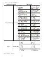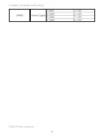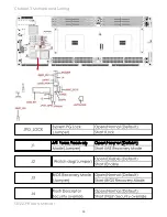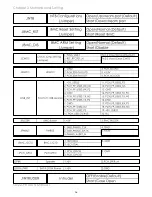
29
Chapter 3 Motherboard Setting
SB122-PH User's Manual
This section describes the jumpers, internal connectors, and internal LEDs
setting on Libra motherboard. Motherboard layout and important jumper
settings are listed as below.
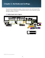
3�1 Motherboard block diagram
Chapter 3� Motherboard Settings
AST_USB Port #0~1 to PCH Port #4~5
NT5CB128M16FP-DI
DDR3 x16
LGA2011-3 Socket
SPI Flash
W25Q64BVSSIG
CPU TDP 145W
SPI
Platform Environment Control Interface(PECI)
VGA CONN
VGA Pin Header
DMI2 x 4
S25FL256SAGMFI001
Flash
Haswell-EP(Broadwell-EP)
Debug port
(INTERNAL Box Header )
USB(X2)
(FRONT Connector )
USB#3
USB#2
ECC DDR 4 (1333/1600/2133/2400)
CPU0
MUX
PCI Express x 1
i210
PCI Express x 1
i217
NCSI
USB#0
USB#1
DIMM #A0
DIMM #A1
DIMM #B0
DIMM #B1
DIMM #C0D
IMM #D0
CPU1_VRD
VR12.5
Haswell-EP(Broadwell-EP)
CPU1
LGA2011-3 Socket
DIMM #E0
CPU TDP 145W
DIMM #F0D
IMM #G0
DIMM #G1
DIMM #H0
DIMM #H1
ECC DDR 4 (1333/1600/2133/2400)
TDP 6.1W
Wellsburg
PCH
Port1(IOU2)
PCI-E Gen3 @8GT/s X8
SFP+ x2
XL710
/82599
SATAPort #0~5
SATA#0
SATA#1
SATA#2
SATA#3
Port 3a x8 support NTB
Golden Finger X16
Golden Finger X16
Port3(IOU1)
PCI-E GEN3 @8GT/s X16
Port2(IOU0)
PCI-E GEN3 @8GT/s X16
Port 3a x8 support NTB
Golden Finger X16
Golden Finger X16
Port3(IOU1)
PCI-E GEN3 @8GT/s X16
Port2(IOU0)
PCI-E GEN3 @8GT/s X16
Aspeed AST2400
I2C4
RJ45 x2
PCI Express x 1
LPC
COM1
(DB-9 CONN)
Box Header
Pin Header
BMC Debug
COM2
(1x3 pin)
JCOM4
(2x5 pin)
CPU0_VRD
VR12.5
Platform Environment Control Interface(PECI)
@6Gb/s
COM1
Rear IO
P1 Port2
P1 Port3
P0 Port2
P0 Port3
P1 CH2/DIMM0/A0
P1 CH3/DIMM1/AA
P1 CH3/DIMM0/A8
P1 CH2/DIMM1/A2
P1 CH0/DIMM0/A0
P1 CH1/DIMM0/A8
P0 CH0/DIMM0/A0
P0 CH0/DIMM1/A2
P0 CH1/DIMM0/A8
P0 CH1/DIMM1/AA
P0 CH2/DIMM0/A0
P0 CH3/DIMM0/A8
CPU0
CPU1
Placement
SATA#4
SATA#5
USB2.0 Port #0~3
USB(X2)
@5Gb/s
LM95241CIMM
LM95241CIMM-1
ADM213
ADM213
COM5
USB2.0 Port #4~5
NCSI
Network Controller Sideband Interface (NCSI)
USB3.0 Port #1
、
2
、
5
、
6
ADM213
COM4
LCM
Pin Header
(1x5 pin)
DMI GEN2@5GT/s
Summary of Contents for SB122-PH
Page 1: ...SB122 PH Storage Server Barebone User s Manual UM_SB122 PH_v 2_122215...
Page 9: ...2 Chapter 1 Product Introduction 1 2 Specifications...
Page 11: ...4 SB122 PH User s Manual Chapter 1 Product Introduction Rear Panel...
Page 12: ...5 Chapter 1 Product Introduction SB122 PH User s Manual Major Components...
Page 37: ...30 Chapter 3 Motherboard Setting SB122 PH User s Manual 3 2 Motherboard block diagram...
Page 38: ...31 Chapter 3 Motherboard Setting SB122 PH User s Manual 3 3 Motherboard Content List...
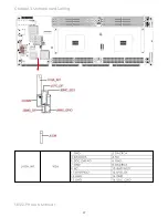
Page 39: ...32 Chapter 3 Motherboard Setting SB122 PH User s Manual 3 4 Internal Connectors Jumpers...
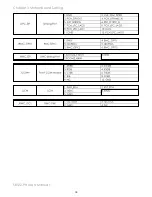
Page 40: ...33 Chapter 3 Motherboard Setting SB122 PH User s Manual...
Page 41: ...34 Chapter 3 Motherboard Setting SB122 PH User s Manual...
Page 42: ...35 Chapter 3 Motherboard Setting SB122 PH User s Manual...
Page 43: ...36 Chapter 3 Motherboard Setting SB122 PH User s Manual...
Page 44: ...37 Chapter 3 Motherboard Setting SB122 PH User s Manual...
Page 45: ...38 Chapter 3 Motherboard Setting SB122 PH User s Manual...
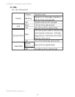
Page 46: ...39 Chapter 3 Motherboard Setting SB122 PH User s Manual 3 5 LEDs 3 5 1 Front Panel LED...
Page 47: ...40 Chapter 3 Motherboard Setting SB122 PH User s Manual 3 5 2 Rear Panel LED...
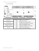
Page 48: ...41 Chapter 3 Motherboard Setting SB122 PH User s Manual 3 5 3 Internal LEDs...
Page 55: ...Chapter 5 BMC Configuration and Settings SB122 PH User s Manual 3 Input subnet mask address...
Page 69: ...Chapter 6 Hardware Introduction SB122 PH User s Manual 6 3 Drive Slot Map...

