XII. INDOOR AIR FLOW DATA
Direct-drive blower models are shipped factory wired for the proper speed at a typical
external static. See Blower Performance Data. Belt-drive blower models have motor
sheaves set for proper CFM at a typical external static.
XIII.CRANKCASE HEAT (OPTIONAL)
Crankcase heat is not required on scroll type compressors, but may be necessary for
difficult starting situations.
XIV.PRE-START CHECK
1. Is unit properly located and slightly slanted toward indoor condensate drain?
2. Is ductwork insulated, weatherproofed, with proper spacing to combustible materi-
als?
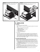
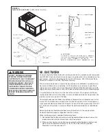
3. Is air free to travel to and from outdoor coil? (See Figure 3.)
4. Is the wiring correct, tight, and according to unit wiring diagram?
5. Is unit grounded?
6. Are field supplied air filters in place and clean?
7. Do the outdoor fan and indoor blower turn freely without rubbing, and are they tight
on the motor shafts?
8. Are the compressor shipping supports removed (if so equipped)?
XV. STARTUP
1. Turn thermostat to “OFF,” turn “on” power supply at disconnect switch.
2. Turn temperature setting as high as it will go.
3. Turn fan switch to “ON.”
4. Indoor blower should run. Be sure it is running in the right direction.
5. Turn fan switch to “AUTO.” Turn system switch to “COOL” and turn temperature set-
ting below room temperature. Unit should run in cooling mode.
6. Is outdoor fan operating correctly in the right direction?
7. Is compressor running correctly.
8. Check the refrigerant charge using the instructions located on compressor access
panel. Replace service port caps. Service port cores are for system access only and
will leak if not tightly capped.
9. Turn thermostat system switch to proper mode “HEAT” or “COOl” and set thermostat
to proper temperature setting. Record the following after the unit has run some time.
A. Operating Mode _______________________________
B. Discharge Pressure (High)_PSIG
C. Vapor Pressure at Compressor (Low) __________PSIG
D. VaporLine Temperature at Compressor ___________°F.
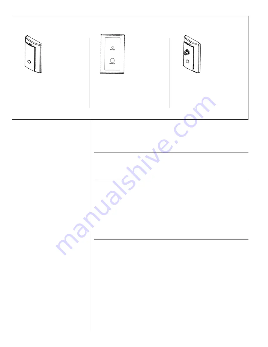
FIGURE 13
FLUSH MOUNT ROOM TEMPERATURE SENSOR FOR NETWORKED DDC APPLICATIONS
(REPLACES THERMOSTAT)
ROOM
TEMPERATURE
SENSOR WITH
TIMED OVERRIDE
BUTTON
ZNS-101
←
10k
Ω
room tem-
perature sensor
transmits room tem-
perature to DDC
system. Times over-
ride buttons allows
tenant to change
from unoccupied
temperature setpoint
to occupied temper-
ature setpoint for a
preset time.
ROOM
TEMPERATURE
SENSOR WITH
TIMED OVERRIDE
BUTTON AND
STATUS INDICATOR
ZNS-102
←
10k
Ω
room tem-
perature sensor
transmits room tem-
perature to DDC
system. Times over-
ride button allows
tenant to change
from unoccupied
temperature setpoint
to occupied temper-
ature setpoint for a
preset time. Status
Indicator Light trans-
mits ALARM flash
code to occupied
space.
ROOM
TEMPERATURE
SENSOR WITH
SETPOINT
ADJUSTMENT AND
TIMED OVERRIDE
BUTTON
ZNS-103
←
10k
Ω
room tem-
perature sensor with
setpoint adjustment
transmits room tem-
perature to DDC
system along with
desired occupied
room temperature
setpoint. Timed
override button
allows tenant to
change from unoc-
cupied temperature
setpoint to occupied
temperature setpoint
for a preset time.
14
Summary of Contents for RLNL-C 13 SEER Series
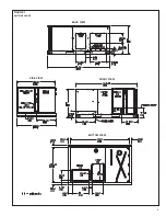
Page 5: ...5 FIGURE 1 UNIT DIMENSIONS BACK VIEW SIDE VIEW FRONT VIEW BOTTOM VIEW ...
Page 39: ...39 FIGURE 14 WIRING DIAGRAM ...
Page 41: ...3 5 TON AIR CONDITIONER 13 14 SEER 41 ...
Page 42: ...4 TON AIR CONDITIONER 13 14 SEER 42 ...
Page 43: ...5 TON AIR CONDITIONER 13 SEER 43 ...
Page 46: ...46 ...
Page 47: ...47 ...
Page 48: ...48 CM 0610 ...


