6
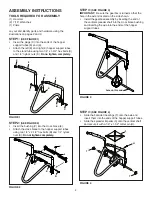
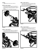
FIGure 9
W
M
P
M
G
W
M
P
M
FIGure 10
K
C
C
N
N A
K
sTeP 10:
(see FIGure 9)
•
Slide a 5/8" washer (M), a spacer (P), another 5/8"
washer (M) and a wheel onto the right side of the axle.
•
Attach the wheel to the axle with a 3/16" x 2" cotter
pin (G).
•
Carefully hammer a hub cap (W) onto the axle.
sTeP 9:
•
Tighten
all loose bolts and nuts at this time.
sTeP 11:
(see FIGure 10)
•
Slide a 5/8" washer (M), a spacer (P), another 5/8"
washer (M) and a wheel onto the left end of the axle.
•
Carefully hammer a hub cap (W) onto the axle.
sTeP 12:
(see FIGure 11)
•
Assemble the handle tubes to the hopper support
tubes using two 1/4" x 1-3/4" hex bolts (C) and 1/4"
nylock nuts (K).
Tighten the bolts.
sTeP 13:
(see FIGure 12)
•
Attach the flow control bracket to the handle tubes
using two 1/4" x 2-3/4" hex bolts (A), four 1/4"
washers (N) and two 1/4" nylock nuts (K).
do not
tighten completely.
FIGure 11
FIGure 12

