5
FIGure 6
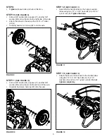
FIGure 5
J
U
O
FIGure 7
C
N
L
K
FIGure 8
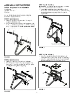
sTeP 5:
(see FIGure 5)
•
Install the flattened end of the drive link rod (AA) into
the hole in the flow plate on the bottom of the hopper.
Lock the rod in the flow plate by rotating the rod.
sTeP 6:
(see FIGure 6)
•
Install the drive link bracket (Z) onto the other end
of the drive link rod (AA). Attach the middle hole in
the drive link bracket to the mounting bracket on the
bottom of the hopper using the 1/4" x 3/4" hex bolt (E)
and a 1/4" nylock nut (K).
Tighten and then loosen
the nut just enough for the drive link bracket to pivot.
sTeP 7:
(see FIGure 7)
•
Place the hopper onto the hopper support tubes,
inserting the vertical spreader shaft up through the
square hole in the bottom of the hopper.
•
Slide the hopper bushing (U) onto the spreader shaft
and insert it into the bottom of the hopper.
•
Slide the spacer (O) onto the spreader shaft.
•
Install the agitator hairpin (J) in the spreader shaft.
sTeP 8:
(see FIGure 8)
•
Attach the hopper to the hopper support tubes using
four 1/4" x 1-3/4" hex bolts (C), 1/4" washers (N),
nylon washers (L) and 1/4" nylock nuts (K).
Tighten
the four bolts
.
AA
E
K
Z
AA

