Agri-Fab 45-0309 Owner'S Manual Download Page 5

5

FIGuRE 7

FIGuRE 4

8.  Fasten  the  hitch  tubes  together  using  three  5/16"  x          

2-1/4"  hex  bolts  and  5/16"  nylock  hex  nuts. 

Do  not 

tighten yet.

 See figure 4.

FIGuRE 5

(L) 5/16" NYLOCK

HEX NUT (3)

(B) 5/16" x 2-1/4"

HEX BOLT (3)

(L) 5/16" NYLOCK

HEX NUT (2)

(V) HAIR COTTER

PIN (1/8")

(HH) HITCH PIN

(C) 5/16" x 2"

HEX BOLT (2)

12. Assemble a 1/2" flat washer, a wheel, another 1/2" flat 

washer and then a 1/2" jam nut onto a 1/2" x 4" hex bolt. 

Tighten the nut finger tight and then back off 1/4 to 1/2 
turn. See figure 6.

13. Assemble the bolt and wheel to the transport tube using 

a 1/2" nylock jam nut. 

Tighten

 the nut but don't collapse 

the tube. See figure 6.

FIGuRE 6 

TRAnSPORT

TuBE

(N) 1/2" NYLOCK

JAM NUT

(R) 1/2" FLAT

WASHER

(A) 1/2" x 4"

HEX BOLT

(M) 1/2" HEX

JAM NUT

16. Screw a 1/4" nylock hex nut all the way onto the flow 

control link. Assemble the ferrule onto the link and then 
start a 1/4" nylock hex nut one or two turns onto the link. 

See figure 7.

17. Assemble the ferrule into the hole at the end of the flow 

control lever using a 1/4" nylock hex nut. 

Tighten

 the 

nut, leaving it loose enough that the ferrule can pivot. 

See figure 7.

18. Assemble the grip onto the end of the flow control lever. 

See figure 7.

FLOw
COnTROL
LEVER

(K) 1/4" NYLOCK

HEX NUT

(K) 1/4" NYLOCK

HEX NUT

(K) 1/4" NYLOCK

HEX NUT

(DD) FERRULE

(CC) FLOW

CONTROL

LINK

(EE) GRIP

EnGLISH

14. If the wheel does not spin freely,  back off the nylock jam 

nut and then the plain jam nut 1/4 to 1/2 turn each.

15. Assemble a wheel to the other side. See figure 6.

9.  Assemble the hitch brackets to the hitch tubes using two 

5/16" x 2" hex bolts and 5/16" nylock hex nuts. 

Do not 

tighten.

 See figure 5. 

10. Assemble the hitch pin through the hitch brackets and 

secure with the hair cotter pin. See figure 5. 

ImPORTAnT:  Do  not

  collapse  the  flat  ends  of  the  hitch 

tubes when tightening the bolts in the next step.

11. 

T

ighten

, but do not overtighten

 the two 5/16" x 1-1/2" 

hex bolts assembled in figure 1. 


T

ighten

, but do not overtighten

 the two 5/16" x 1-3/4" 

hex bolts assembled in figures 2 and 3. The lift handle 

must be able to pivot.


T

ighten

 the hex bolts assembled in figure 4 and 5.

For Agri Fab Discount Parts Call 606-678-9623 or 606-561-4983

www.mymowerparts.com

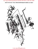
Summary of Contents for 45-0309

Page 1: ...ette notice PRINTED IN U S A 32 POLY SPIKER SPREADER owners manual ManUAL DEL USUARIO NOTICE D UTILISATION Model No Modelo No Mod le No 45 0309 the fastest way to purchase parts www speedepart com FOR...

Page 2: ...micals Always begin with the transmission in first low gear and graduallyincreasespeedasconditionspermit Maximum towing speed 10 M P H Do not drive too close to a creek or ditch and be alert for holes...

Page 3: ...Nut 1 2 N 2 Nylock Jam Nut 1 2 O 2 Flat Washer 1 4 P 2 Nylon Washer 21 64 Q 4 Flat Washer 5 16 R 4 Flat Washer 1 2 S 10 Flat Washer 5 8 T 3 Cotter Pin 1 8 x 1 1 2 U 1 Cotter Pin 3 32 x 3 4 V 1 Hair Co...

Page 4: ...front hole in the right hand side of the hopper using a 5 16 x 1 1 2 hex bolt a 5 16 flat washer and a 5 16 nylock hex nut Assemble the bolt and washer from inside the hopper Do not tighten yet See fi...

Page 5: ...ver using a 1 4 nylock hex nut Tighten the nut leaving it loose enough that the ferrule can pivot See figure 7 18 Assemble the grip onto the end of the flow control lever See figure 7 FLOw COnTROL LEV...

Page 6: ...rear bolts See figure 8 FLOw COnTROL LEVER FEED PLATE P NYLON WASHER K 1 4 NYLOCK HEX NUT K 1 4 NYLOCK HEX NUT K 1 4 NYLOCK HEX NUT U 3 32 x 3 4 COTTER PIN CC FLOW CONTROL LINK II EXTENSION SPRING 24...

Page 7: ...langed bearing in the end plate See figure 14 FIGURE 13 FIGURE 14 FIGURE 15 IMPORTANT When assembling the spike disks be sure they face in the direction shown in the instructions 34 Place two spike di...

Page 8: ...flanged bearings in the disks See figure 17 FIGURE 16 FIGURE 17 37 Place two 5 8 flat washers separated by a long spacer tube onto the shaft See figure 18 FIGURE 18 BB LONG SPACER TUBE S 5 8 FLAT WASH...

Page 9: ...rt spacer tube onto the shaft Fit the short spacer tube onto the ends of the flanged bearings in the spike disk and in the end plate Push the shaft on through the flanged bearing in the end plate See...

Page 10: ...aterial package and to the instruction decal on your spreader to help determine the proper spreader setting and application rate AlsoseetheSettingChartonthispageforageneral range of settings for commo...

Page 11: ...locidad y aumente la velocidad gradualmente como lo permitan las condiciones La velocidad m xima de remolque es 10 M P H 16 kil metros por hora No opere el equipo muy cerca de arroyos o zanjas y est a...

Page 12: ...5 12 Instale una arandela plana R una rueda otra arandela plana R y entonces una contratuerca M sobre un tornillo hexagonal A Apriete la contratuerca hasta el final con sus dedos y entonces h gala re...

Page 13: ...e dos discos surcadores separados por un tubo espaciadorlargo BB sobreeleje Asegureeltuboespaciador de metal sobre los extremos de los cojinetes de brida en los discos Vea la Figura 15 35 Coloque una...

Page 14: ...materiales y la calcoman a de instrucciones en el esparcidor para determinar el ajuste apropiado del esparcidor y la velocidad de aplicaci n Tambi n vea en el Cuadro de Ajuste de esta p gina una gama...

Page 15: ...rs avec la bo te de vitesse en premi re vitesse basse et augmenter graduellement la vitesse selon les conditions Vitesse maximale de remorquage 16 km h 10 milles hr Ne pas conduire trop pr s d un ruis...

Page 16: ...ec la goupille en pingle cheveux V Voir la figure 5 12 Monter une rondelle plate R une roue une autre rondelle plate R et enfon un contre crou M sur un boulon 6 pans A Serrer l crou avec la main puis...

Page 17: ...r deux disques de crampon s par s par un long tube entretoise BB sur l arbre Installer le un long tube entretoise sur les extr mit s des paliers bride dans les disques Voir la figure 15 35 Placer une...

Page 18: ...l tiquette d instructions sur l emballage du mat riau et l autocollant d instructions sur la r pandeuse pour aider d terminer le r glage et le taux d application appropri s de la r pandeuse En outre...

Page 19: ...19 NOTES For Agri Fab Discount Parts Call 606 678 9623 or 606 561 4983 www mymowerparts com...

Page 20: ...21 14 13 7 8 8 9 13 17 49 50 51 52 53 54 55 18 28 29 33 35 36 37 38 39 40 41 42 30 31 22 23 25 23 26 27 42 42 43 43 44 44 46 47 48 45 56 57 57 58 59 58 58 15 59 43 34 43 54 43 58 59 F B 42 32 24 C 20...

Page 21: ...7959 1 Link Flow Control 34 47969 1 Ferrule 5 16 Thread x 1 4 Hole 35 43224 3 Bolt Hex 5 16 x 2 1 4 36 44180 2 Bolt Hex 5 16 x 2 37 43085 2 Bolt Hex 5 16 x 1 1 2 38 43084 2 Bolt Hex 5 16 x 1 3 4 39 43...

Page 22: ...22 For Agri Fab Discount Parts Call 606 678 9623 or 606 561 4983 www mymowerparts com...

Page 23: ...For Agri Fab Discount Parts Call 606 678 9623 or 606 561 4983 www mymowerparts com...

Page 24: ...the Berne convention No part of this document may be reproduced or transmitted in any form or by an means electronic or mechanical including photocopying or recording or by any information storage or...

Reviews: