background image

15

ASP   

USER MANUAL

ITEM

FUNCTION

DESCRIPTION

2, 4

Reticle Position Zeroing Simultaneously holding down buttons (2) and (4) zeroes the 

reticle position to the center of the screen.

Left, Right

Use the LEFT (4) and RIGHT (2) buttons to navigate through 

the items on the menu.

5

OK

Push the OK button (5) to view the settings available for the 

item selected. 

MENU 

Pushing and holding button (5) will bring up the Main Menu 

selection. The menu includes the following functions: 

Palette, Temperature, Reticle, Boresight, Scenarios, 

Corrections and Settings. 

UCMNUC/ FFC Process  

Interruption

Pushing button (5) when the countdown is on the screen 

will cancel the UCMNUC/ FFC and the shutter will not 

interrupt viewing.

2.2.2  MAIN MENU

Most setup options can be accessed from the MAIN MENU. 
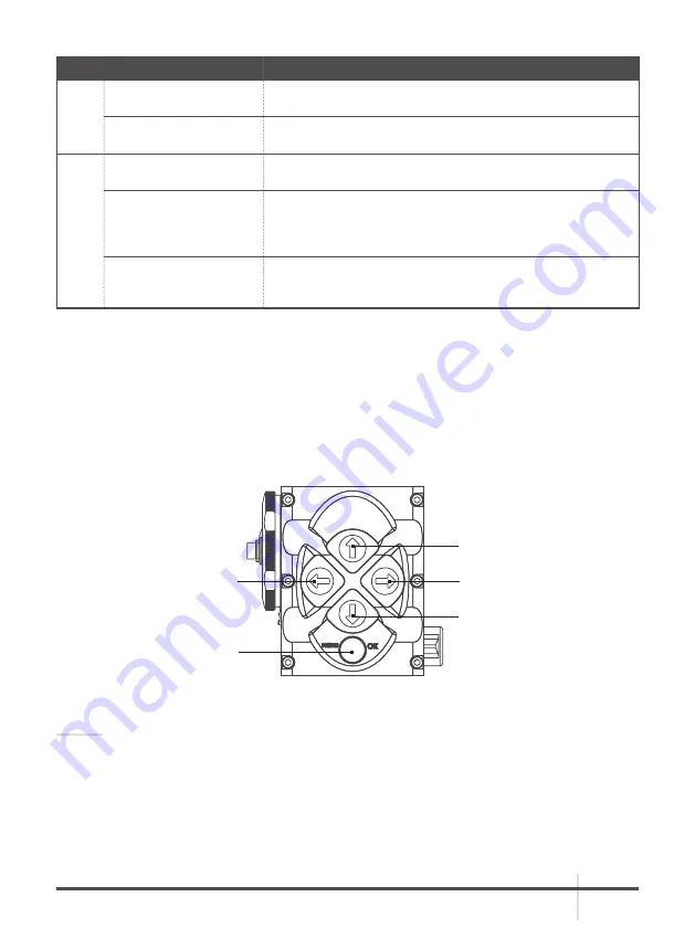
To display the MAIN MENU, push and hold down the MENU button (5) on the control panel (Figure 

2-7). Push and hold down the MENU button again to exit the menu.
Once the MAIN MENU is displayed (Figure 2-8), use the UP and DOWN buttons (Figure 2-7) to 

navigate through the items on the menu.
Push the OK button to view the settings available for the item selected.

NOTES:

Navigate through submenu items by pushing the UP and DOWN button, except where otherwise 

expressly indicated. The LEFT and RIGHT buttons are available only when specified on the 

menu screen with < > symbols.
After a menu item is selected, push the OK button to make the selected setting/ activate the 

selected function.
Select the EXIT item and then push the OK button to return to the MAIN MENU.

FIGURE 2-7. MAIN MENU NAVIGATION BUTTONS

(1) UP

(3) DOWN 

(4)  LEFT  

(5) MENU/OK 

(2) RIGHT

Summary of Contents for ASP

Page 1: ...USER MANUAL ASP THERMAL IMAGING MONOCULAR...

Page 2: ...ted to the Export Administration Regulations the International Economic Emergency Powers Act and various U S embargoes and sanctions AGM Global Vision products may not be exported re exported or trans...

Page 3: ...atures 9 2 OPERATING INSTRUCTIONS 10 2 1 Installation and Mounting 10 2 2 Controls and Display Indications 13 2 3 Operating Procedures 20 3 MAINTENANCE AND TROUBLESHOOTING 23 3 1 Operator Troubleshoot...

Page 4: ...DO NOT force the equipment controls past their stopping points DO NOT leave the equipment activated during breaks in operation DO NOT store the equipment with the batteries installed Thoroughly clean...

Page 5: ...presents three versions of the device equiped with objective lenses with 25mm 50mm and 75mm focal length The main optical electronic components of the Asp include an objective Germanium thermal lens e...

Page 6: ...k can also be connected to the Asp Figure 1 2 shows the Asp The ITEM NO column of Table 1 1 indicates the number used to identify items in Figure 1 2 NOTE Here and below the example used is the Asp wi...

Page 7: ...gure 1 3 TABLE 1 2 STANDARD COMPONENTS ITEM DESCRIPTION QUANTITY 1 Asp Thermal Imaging Monocular 1 2 Objective Lens Cap 1 3 Eyecup 1 4 Battery Cassette 2 5 CR123A Lithium Battery 2 6 Wireless Remote C...

Page 8: ...he PART NO column indicates the primary number used by the manufacturer to identify an item TABLE 1 3 OPTIONAL EQUIPMENT ITEM DESCRIPTION PART NO 1 AGM WiFi Attachment 6305WIF1 2 AGM HD Recorder 6305H...

Page 9: ...led Manual Non Uniformity Correction Flat Field Correction UCMNUC FFC Current operational state information display battery status active profile palette setting Wireless remote control Analog video i...

Page 10: ...polarity symbols on the batteries with the polarity symbols on the cassette 4 Insert the cassette with installed batteries 5 Replace the battery cap 2 1 2 FASTENING AN WIRELESS REMOTE CONTROL Using t...

Page 11: ...emoving the batteries Remove the connector protective cap see Figure 1 2 Connect a cable of the external 5V battery bank to the Asp Micro USB connector Connect a cable of Digital Video Recorder WiFi A...

Page 12: ...dard OD double pole socket with a positive central contact CAUTION After removing the cable replace the protective cap over the connector 2 1 5 INSTALLING THE ASP ON A TRIPOD To mount the Asp to a tri...

Page 13: ...covered with 2 turns of the ring 2 Operation Switch Activates the Asp when turned to ON Activates Standby mode when turned to STB Deactivates the Asp when turned to OFF 3 Control Panel Buttons Configu...

Page 14: ...r up respectively There are 13 palettes available White Hot Black Hot Fusion Rainbow Globow Ironbow 1 Ironbow 2 Sepia Color 1 Color 2 Ice Fire Rain OEM Custom User Controlled Manual Non Uniformity Cor...

Page 15: ...2 2 MAIN MENU Most setup options can be accessed from the MAIN MENU To display the MAIN MENU push and hold down the MENU button 5 on the control panel Figure 2 7 Push and hold down the MENU button aga...

Page 16: ...inversion White Hot mode is good for spotting targets while Black Hot mode is most useful for situational reading NOTE Training and experience are required to quickly and properly interpret the therm...

Page 17: ...oss Center Dot Cross Crosshair To select the reticle type push the LEFT or RIGHT button Push the OK button to confirm selection EXIT CROSS RETICLE FIGURE 2 11 RETICLE MENU Boresight Menu The boresight...

Page 18: ...Figure 3 14 allows the user to select from a choice of filter patterns The different field environments are pre set with the correction filters valued for the best field performance The icon of the se...

Page 19: ...STANDARD function allows the user to select from a choice of NTSC or PAL video standard The LEFT MARGIN function allows the user to move the display left right by a fixed number of pixels The TOP MARG...

Page 20: ...itch ON After approximately 3 sec video of the thermal scene should appear 5 Adjust the Asp for your eyesight by turning the eyepiece focus ring CW up to the stop and then CCW until the display and sy...

Page 21: ...utton 2 to scroll through available palettes The palette name will appear in the top part of the display E Turns reticle ON OFF Push and hold button 2 to turn reticle ON or OFF F Select the color of t...

Page 22: ...lows 1 Be sure to save your settings and data 2 Turn off the Asp 3 Place the protective cap on the objective lens 4 Disconnect the cable if applicable 5 Place the protective cap on the connector 6 Rem...

Page 23: ...Insert batteries or install correctly Batteries are dead Replace the batteries Batteries surfaces or contacts are dirty or corroded Clean the contact surfaces with a pencil eraser and or alcohol and c...

Page 24: ...in this section CAUTION The Asp is a precision electro optical instrument and must be handled carefully at all times to prevent damage CAUTION DO NOT dismantle the equipment 3 2 2 CLEANING PROCEDURES...

Page 25: ...Using a screwdriver unscrew the four screws A Figure 4 1 that secure the cover to the bottom of the unit Remove the cover 2 Replace the battery with new one CR2032 3V Install the battery aligning thei...

Page 26: ...nly to the original purchaser Any breach of this warranty shall be enforced unless the customer notifies AGM Global Vision at the address noted below within the applicable warranty period The customer...

Page 27: ...g box Please include a letter that indicates your RMA the Customer s Name a Return Address reason for the return contact information valid telephone numbers and or an e mail address and proof of purch...

Page 28: ...ng Modes Image Palettes White Hot Black Hot Fusion Rainbow Globow Ironbow 1 Ironbow 2 Sepia Color 1 Color 2 Ice Fire Rain and OEM Analog Video Input Output Format resolution PAL 768 574 pixels NTSC 64...

Page 29: ...36 ASP TB75 640 Overall Dimensions 196 72 56 mm 7 7 2 8 2 2 in 220 72 60 mm 8 6 2 8 2 3 in 248 89 89 mm 9 7 3 5 3 5 in Weight w o Batteries 0 58 kg 1 2 lb 0 69 kg 1 5 lb 0 83kg 1 8 lb TABLE 5 5 ENVIRO...

Page 30: ...NO 1 25mm Objective Lens Cap GOL25OBLCP 50mm Objective Lens Cap GOL50OBLCP 75mm Objective Lens Cap GOL75OBLCP 2 25mm Objective Lens Assembly GOL25OBLAS 50mm Objective Lens Assembly GOL50OBLAS 75mm Obj...

Page 31: ......

Page 32: ...173 West Main Street PO Box 962 Springerville AZ 85938 USA Tel 1 928 333 4300 info agmglobalvision com www agmglobalvision com EUROPEAN OFFICE Andrey Lyapchev 7 Sofia P C 1756 Bulgaria Tel 35 988 412...

Reviews: