


U1401A Quick Start Guide
Performing Resistance Measurement and Continuity Test
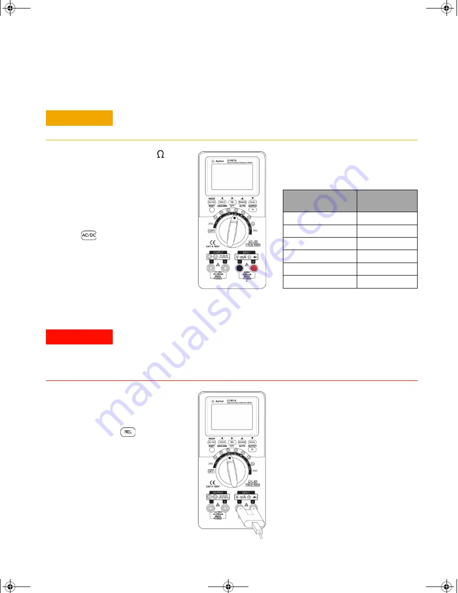
Performing Temperature Measurements
C A U T I O N
Disconnect circuit power and discharge all high-voltage capacitors before measuring
resistance to prevent possible damage to the instrument or the device under test.
WA R N I N G
• Before measuring the temperature of a circuit or device, disconnect its power.
• The bead type thermocouple probe is suitable for measuring temperature from
–40 °C to 204 °C in PTFE compatible environments. The probes may emit toxic
gas above this temperature range.
1
Set the rotary switch to
.
2
Connect the red (+) and black
(–) test leads to the
INPUT
terminals.
3
Probe the resistor (or shunt)
leads and read the display.
4
To perform continuity test,
press
to toggle the
audible continuity function
on
or
off
.
For continuity test, the instrument will
beep if the resistance is less than the
values indicated below:
Measurement range
Resistance
threshold
500.00
Ω
10
Ω
5.0000 k
Ω
100
Ω
50.000 k
Ω
1 k
Ω
500.00 k
Ω
10 k
Ω
5.0000 M
Ω
100 k
Ω
50.000 M
Ω
1 M
Ω
1
Set the slide switch to the
M
position to disable the output.
2
Set the rotary switch to
mV
.
3
Press and hold
for more
than 1 second.
4
Plug the thermocouple probe
(with adapter) into the
INPUT
terminals.
5
Touch the surface to be
measured with the
thermocouple probe and read
the display.
Best practices:
•
Do not bend the thermocouple
leads at sharp angles.
Repeated bending may break
the leads.
•
Do not immerse the
thermocouple probe in any
liquid.
•
Clean the surface to be
measured and make sure that
the probe is securely touching
the surface.
U1401A QSG.fm Page 3 Tuesday, May 15, 2012 11:10 AM