


2
Installation
Setup and interconnects: cable installation
20
Seahorse XFe Analyzer Operating Manual
Setup and interconnects: cable installation
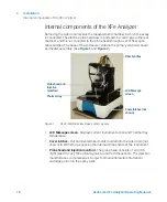
The XFe Analyzer is operated from a touch screen computer monitor mounted to
a stand, referred to as a controller. One RS232 cable and one USB cable handle
the communication of commands and data between the instrument and the
controller.
The controller may be connected to an external network, through the ports on the
underside.
“Unpacking and Component Identification”
on page 14 to identify each
cord, and refer to the figures below to identify the connectors.
1
Connect power cords: One power cord is used to connect the instrument to a
grounded AC (mains) outlet. A second power cord is used to connect the
controller power supply module to the AC supply. The power supply module
is then connected to the socket at the bottom of the controller.
(See
2
Connect the data cables to the analyzer. One RS232 cable connects the
controller serial port to the analyzer socket labeled "COM." (See
.)
3
A second cable (USB) connects the analyzer socket labeled "USB" to the USB
port on the controller directly adjacent to the network (Ethernet) port. This
port must be used for proper functioning of the instrument and barcode
reader. (See
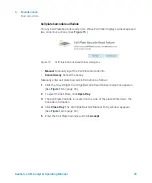
Figure 3.
Controller ports (underside)
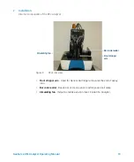
Figure 4.
XFe rear panel - USB and serial ports
Serial port
Network port
Power input
USB ports (4)
Serial port for
controller
connection
USB ports from
barcode reader
Summary of Contents for Seahorse XFe
Page 1: ...Seahorse XFe Analyzer Operating Manual...
Page 4: ...4 Seahorse XFe Analyzer Operating Manual...
Page 12: ...1 Introduction Technical Specifications 12 Seahorse XFe Analyzer Operating Manual...
Page 38: ...4 Maintenance Additional Resources 38 Seahorse XFe Analyzer Operating Manual...
Page 39: ......


