background image

Service Guide E8364-90001

4- 55

PNA Series Microwave Network Analyzers

     Troubleshooting

E8362A, E8363A, E8364A

Instrument Block Diagrams

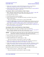
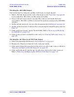
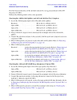
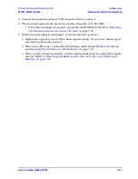
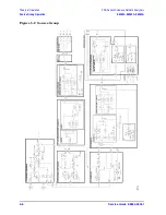
E8362A Overall Block Diagram, Includes Options UNL and 014

Insert into side-2 of pocket-sleeve: fold-out/fold-up; 22 x 34; m120blk_014.pdf

Summary of Contents for E8362A

Page 1: ...Agilent Technologies PNA Series Microwave Network Analyzers E8362A E8363A E8364A Part Number E8364 90001 Printed in USA March 2003 Supersedes June 2002 Copyright 2002 2003 Agilent Technologies Inc All rights reserved ...

Page 2: ...MENT THAT CONFLICT WITH THESE TERMS THE WARRANTY TERMS IN THE SEPARATE AGREEMENT WILL CONTROL Certification Agilent Technologies Inc certifies that this product met its published specifications at the time of shipment from the factory Agilent Technologies Inc further certifies that its calibration measurements are traceable to the United States National Institute of Standards and Technology to the...

Page 3: ...G Warning denotes a hazard It calls attention to a procedure which if not correctly performed or adhered to could result in injury or loss of life Do not proceed beyond a warning note until the indicated conditions are fully understood and met CAUTION Caution denotes a hazard It calls attention to a procedure that if not correctly performed or adhered to could result in damage to or destruction of...

Page 4: ...nd Quick Start Guide contains procedures for installing configuring and verifying the operation of your analyzer The CD ROM provides the following Installation and Quick Start Guide Service Guide Help system Help system in pdf format for printing Network Analyzer Product Overview multimedia presentation Optional Documentation The optional printed version of the Service Guide provides information o...

Page 5: ...Upgrades and Accessories 2 3 How to Order an Upgrade 2 3 Option 010 Time Domain 2 3 Option 014 Configurable Test Set 2 3 Option 099 Firmware Upgrade 2 4 Option UNL Source Attenuators and Bias Tees 2 4 CD RW Drive 2 4 USB Hub 2 4 Option AVK Printed User s and Programmer s Guide 2 4 Option 0BW Printed Service Guide 2 5 Option 1CP Rack Mount Flange Kit for Instruments with Handles 2 5 Option 1CM Rack...

Page 6: ...30 Source Power Linearity Test 3 31 Frequency Accuracy Test 3 31 Trace Noise Test 3 32 Receiver Compression Test 3 32 Noise Floor Test 3 33 Calibration Coefficient Test 3 34 System Crosstalk Test 3 35 Dynamic Accuracy Test 3 35 Power Meter Accuracy Test 3 37 Adjustments 3 42 Source Calibration Adjustment 3 43 Receiver Calibration Adjustment 3 44 LO Power Adjustment 3 47 10 MHz Frequency Reference ...

Page 7: ...eration 5 3 Functional Groups of the Network Analyzer 5 3 Source Group Operation 5 5 Band Modes 5 5 A8 Fractional N Synthesizer Board 5 7 A17 L O Multiplier Amplifier 10 LOMA 10 5 8 A18 Multiplier Amplifier 20 MA 20 5 8 A19 Splitter 5 8 A20 L O Distribution Assembly LODA 5 8 A10 Frequency Reference Board 5 8 A11 Phase Lock Board 5 9 A12 Source 20 5 9 A21 Source Multiplier Amplifier 50 SOMA 50 E836...

Page 8: ...ion UNL 014 6 33 Bottom RF Cables Option UNL 014 Continued 6 34 Bottom Cables Ribbon and Wrapped Wire 6 36 Internal Hardware and Parts 6 38 Hard Disk Drive Assembly 6 40 Rear Panel Assembly 6 41 External Parts 6 42 Miscellaneous Part Numbers 6 44 Miscellaneous Part Numbers Continued 6 45 7 Repair and Replacement Procedures Information in This Chapter 7 2 Chapter Seven at a Glance 7 2 Before Starti...

Page 9: ...Mixer Bias Board 7 48 Removing and Replacing the A31 A32 A33 and A34 Receiver Modules 7 50 Removing and Replacing the A35 Receiver Motherboard 7 52 Removing and Replacing the A36 and A37 60 dB Step Attenuators Option UNL 7 54 Removing and Replacing the A38 and A39 Bias Tees Option UNL 7 56 Removing and Replacing the A40 Floppy Disk Drive 7 58 Removing and Replacing the A41 Hard Disk Drive 7 60 Rem...

Page 10: ... in This Appendix C 2 Appendix C at a Glance C 2 How to Check the Current Firmware Version C 2 Downloading from the Internet C 2 Downloading Using Option 099 Firmware Upgrade C 3 Installation Requirements C 3 Downloading from a USB CD Drive Connected to the Analyzer C 3 Downloading from a Shared CD Drive Over the LAN C 3 Downloading Over the LAN C 4 D Operating System Recovery Information in This ...

Page 11: ...Service Guide E8364 90001 1 1 1 Safety and Regulatory Information ...

Page 12: ...scriptions of CAUTION and WARNING symbols used throughout this manual Page 1 3 General Safety Considerations A list of safety points to consider when servicing your network analyzer Page 1 3 Electrostatic Discharge Protection A discussion of electrostatic discharge ESD and related recommendations and requirements for ESD protection Page 1 5 Regulatory Information Definitions of instrument markings...

Page 13: ...et General Safety Considerations Safety Earth Ground WARNING This is a Safety Class I product provided with a protective earthing ground incorporated in the power cord The mains plug shall only be inserted in a socket outlet provided with a protective earth contact Any interruption of the protective conductor inside or outside of the instrument will make the instrument dangerous Intentional interr...

Page 14: ...batteries according to manufacturer s instructions WARNING Procedures described in this document may be performed with power supplied to the product while protective covers are removed Energy available at many points may if contacted result in personal injury WARNING The power cord is connected to internal capacitors that may remain live for 10 seconds after disconnecting the plug from its power s...

Page 15: ...king connections always wear a heel strap when working in an area with a conductive floor If you are uncertain about the conductivity of your floor wear a heel strap always ground yourself before you clean inspect or make a connection to a static sensitive device or test port You can for example grasp the grounded outer shell of the test port or cable connector briefly always ground the center con...

Page 16: ...age 2 9 for assistance The instruction documentation symbol The product is marked with this symbol when it is necessary for the user to refer to the instructions in the documentation The CE mark is a registered trademark of the European Community If accompanied by a year it is when the design was proven The CSA mark is a registered trademark of the Canadian Standards Association This is a marking ...

Page 17: ...Emissions Requirements This network analyzer complies with German FTZ 526 527 Radiated Emissions and Conducted Emission requirements Compliance with German Noise Requirements This is to declare that this instrument is in conformance with the German Regulation on Noise Declaration for Machines Laermangabe nach der Maschinenlaermrerordung 3 GSGV Deutschland Acoustic Noise Emission Geraeuschemission ...

Page 18: ...1 8 Service Guide E8364 90001 Safety and Regulatory Information PNA Series Microwave Network Analyzers Regulatory Information E8362A E8363A E8364A ...

Page 19: ...Service Guide E8364 90001 2 1 2 General Product Information ...

Page 20: ... 3 Analyzer Options Upgrades and Accessories A list of the options and upgrades available for the microwave network analyzers Page 2 3 Required Service Test Equipment A list of service equipment that is required to perform system verification performance tests adjustments and troubleshooting Page 2 6 Agilent Support Services and Assistance The Internet address URL for on line assistance Telephone ...

Page 21: ...r example E8364AU The desired option from the available list For example Time Domain Individual upgrade kits are also available and can be ordered by part number Refer to Upgrade Kits on page 6 45 for a complete list of available kits Option 010 Time Domain An Option 010 analyzer can display the time domain response of a network or test device by calculating the inverse Fourier transform of the fr...

Page 22: ...ternal computer connected to a Local Area Network LAN This firmware is also available on the Internet at the Agilent website http www agilent com find pna Select your analyzer s model number in this website to view available upgrades Option UNL Source Attenuators and Bias Tees This option adds a 60 dB step attenuator and a bias tee between the switch splitter and each of the ports The step attenua...

Page 23: ...ns a pair of flanges cut to adapt to handles rack mount rails and the necessary hardware to mount the analyzer in an equipment rack with 482 6 mm 19 inches horizontal spacing Additional kits may be ordered from Agilent Refer to Rack Mount Kits and Handle Kits on page 6 45 for the part numbers Option1CM RackMount FlangeKit for Instruments without Handles Option 1CM is a rack mount kit that contains...

Page 24: ...ests except Dynamic Accuracy Test This test requires a power meter with Option G12 or H12 that has been certified to a higher accuracy specification If an Option G12 or H12 power meter is not available a test is provided on page 3 43 to verify the accuracy of a standard power meter E4418A 19Ad d If an accurate measurement of the dynamic accuracy specification is not required the E4418A or E4419A c...

Page 25: ...C D None P A Adapters 3 5 mm f to 3 5 mm f E8362A Return Loss 32 dΒ 83059B 85052 60012c P A T 3 5 mm f to type N m E8362A Return Loss 28 dΒ 1250 1743 None P A T 2 4 mm f to 2 4 mm f E8363A E8364A Return Loss 26 dΒ 11900B 85056 60007d P A T 2 4 mm f to type N m E8363A E8364A Return Loss 28 dΒ 11903D None P A T Attenuators 3 5 mm m f 10 dB fixed attenuator E8362A Accuracy 0 5 dB Freq 45 MHz to 20 GH...

Page 26: ...c equivalent is 8 mm 1 1 and 2 4 Nm 10 and 21 in lb settings for semi rigid cables N A N A T R 1 inch open end torque wrench metric equivalent is 26 mm 8 1 N m 72 in lb setting for Port 1 and Port 2 connector nuts N A N A R 20 mm open end torque wrench 0 9 N m 8 in lb setting for Port 1 and Port 2 measurement connections 8710 1764 N A P A T Static Safety Parts Adjustable antistatic wrist strap N A...

Page 27: ...05 269 7500 fax 305 269 7599 Canada tel 1 877 894 4414 fax 905 282 6495 Europe tel 31 20 547 2323 fax 31 20 547 2390 Australia tel 1 800 629 485 fax 61 3 9210 5947 New Zealand tel 0 800 738 378 fax 64 4 495 8950 Japan tel 81 426 56 7832 fax 81 426 56 7840 Singapore tel 1 800 375 8100 fax 65 836 0252 Malaysia tel 1 800 828 848 fax 1 800 801 664 India tel 1 600 11 2929 fax 000 800 650 1101 Hong Kong...

Page 28: ...pair Option R 50C 002 Standards Compliant Calibration This option adds a calibration label an ISO 17025 calibration certificate and the corresponding calibration data measurement uncertainties and guardbands on a CD ROM This certificate and data can be obtained by sending your analyzer to Agilent for calibration along with an order for R 50C 002 Refer to Shipping Your Analyzer to Agilent for Servi...

Page 29: ...Service Guide E8364 90001 3 1 3 Tests and Adjustments ...

Page 30: ...er The Agilent N2721A software package must be purchased separately Chapter Three at a Glance Section Title Summary of Content Start Page Before You Begin Items to consider or procedures to perform before testing is begun Verify the Operating Environment Protect Against Electrostatic Discharge ESD Allow the Analyzer to Warm Up Review the Principles of Connector Care Page 3 4 About System Verificat...

Page 31: ...tware Package a A brief summary of each performance test in the Agilent N2721A software package Source Power Accuracy Test Source Power Linearity Test Frequency Accuracy Test Trace Noise Test Receiver Compression Test Noise Floor Test Calibration Coefficient Test System Crosstalk Test Dynamic Accuracy Test Page 3 30 Adjustments Setups and procedures for adjusting your analyzer Source Calibration A...

Page 32: ...each room temperature As the device dimensions change with temperature their electrical characteristics change as well It is necessary to keep the environmental levels within the following limits Temperature 23 C 3 C Error corrected temperature range Once the measurement calibration has been done the ambient temperature must be maintained to within 1 C of the calibration temperature Humidity 5 to ...

Page 33: ...ouch mating plane surfaces Extend sleeve or connector nut Set connectors contact end down Use plastic end caps during storage Store connectors or adapters loose Visual Inspection Do Inspect all connectors carefully Do Not Use a damaged connector ever Look for metal particles scratches and dents Connector Cleaning Do Try compressed air first Do Not Use any abrasives Use isopropyl alcohol Get liquid...

Page 34: ...lection and transmission coefficients System specifications are applicable when the measurement system is used to make error corrected measurements System specifications are verified in one of the following ways Complete the system verification procedure using a certified verification kit or Complete all of the performance tests and certify or recertify the calibration kit that will be used for fu...

Page 35: ...fications If confirmation is successful the analyzer meets the instrument specifications If the calibration kit to be used for measurements is also certified successful completion of the performance tests also ensures that the network analyzer measurement system meets the system specifications Certificate of Calibration Agilent Technologies will issue a certificate of calibration for the product u...

Page 36: ...t stopping to repair or adjust1 Refer to Figure 3 1 for test flow Print data at the completion of all the tests even if you are aware that the analyzer did not pass If there is a failure complete the verification before you troubleshoot repair and adjust After the failure has been corrected repeat the entire system verification or performance tests and generate a new set of data Figure 3 1 ANSI NC...

Page 37: ...verification or performance tests while stopping to troubleshoot Refer to Figure 3 2 for test flow Troubleshoot and repair the first problem encountered without continuing to other tests After you troubleshoot repair and adjust repeat the last failed portion and generate a new set of data Print out the system verification results or complete the performance test record as the analyzer passes each ...

Page 38: ...lity check function of the four receivers switch repeatability check operation of the step attenuators attenuator range check Option UNL only receivers linearity attenuator range check Option UNL only Switch Repeatability Check The check performs a reflection measurement of a short and stores the resulting trace in memory The transfer switch is toggled to the opposite port and back and then anothe...

Page 39: ...Start Port 2 4 The test will prompt you to connect the short 5 The result of the operator s check will be shown as a PASS or FAIL next to the test Figure 3 3 Operator s Check Dialog Box If the Operator s Check Fails 1 Clean the test ports shorts and adapters Torque to specification Repeat the check 2 If the check still fails suspect a faulty component A repeated failure in the switch repeatability...

Page 40: ...t 1 check fails the A25 step attenuator may be faulty If the Port 2 check fails the A26 step attenuator may be faulty Refer to Removing and Replacing the A36 and A37 60 dB Step Attenuators Option UNL on page 7 54 If all ranges of the attenuator check fail suspect a loose connection on the step attenuator control cable If the Port 1 check fails check the A25 step attenuator cable If the Port 2 chec...

Page 41: ...port cable Cable Return Loss Check on page 3 14 Cable Insertion Loss Check on page 3 15 Cable Magnitude and Phase Stability Check on page 3 16 Cable Connector Repeatability Check on page 3 18 Accessories Used in the Test Port Cable Checks Equipment Type Models Used With Model or Part Number Alternate Model or Part Number Calibration kit 3 5 mm E8362A 85052B 85052D RF cable 3 5 mm f to 3 5 mm f E83...

Page 42: ...zer now displays the return loss of the cable 4 From the Marker menu click Marker Search In the Marker Search dialog box in the Search Type box make sure Maximum is selected Click Execute and then click OK 5 The marker annotation on the screen indicates the worst case return loss Refer to the cable manual to see if it meets the return loss specification For an example of a typical return loss meas...

Page 43: ... Minimum Click Execute and then click OK 3 The displayed response is twice the actual loss To get the actual worst case insertion loss divide the value at the marker annotation by two Refer to the cable manual to see if it meets the insertion loss specification For an example of a typical insertion loss measurement see Figure 3 5 Figure 3 5 Typical Cable Insertion Loss Response If the Cable Insert...

Page 44: ...age the measurement 50 times approximately two seconds 9 To normalize the data trace a On the Trace menu click Math Memory b In the Math Memory dialog box click the Data Memory button c In the Data Math list select Data Memory d Under Trace View Options make sure Data Trace is selected e Click OK 10 Slowly make a 180 degree bend in the middle of the cable and hold it in that position 11 For each t...

Page 45: ...2A E8363A E8364A Preliminary Checks Figure 3 6 Typical Cable Magnitude and Phase Stability Response If the Cable Magnitude and Phase Stability Check Fails 1 Clean the cable and devices and torque to specification Repeat the check 2 If the check still fails the cable should be repaired or replaced ...

Page 46: ...make sure Data Trace is selected e Click OK 6 To adjust the display scale a On the Scale menu click Scale b In the Scale Per Division box click the arrow to select 0 5 dB c In the Level box under Reference click the arrow to select 0 dB d Click OK 7 Disconnect and then reconnect the cable to the test port Tighten the connection to the specified torque for the connector type 8 On the Channel menu c...

Page 47: ... Port 2 Check connect the cable with the load attached to Port 2 and repeat steps 2 through 11 Figure 3 7 Typical Cable Connector Repeatability Response If the Cable Connector Repeatability Check Fails 1 Clean the cable and devices and torque to specification Repeat the check 2 If the check still fails the cable should be repaired or replaced ...

Page 48: ...m verification are the sum of the factory measurement uncertainties for the verification devices and the uncertainties associated with the system being verified You can determine your system measurement uncertainty limits by referring to the analyzer embedded on line help IMPORTANT Passing this system verification does not guarantee that the analyzer meets all of its performance specifications How...

Page 49: ... crosstalk The random errors include noise drift connector repeatability and test cable stability A complete description of system errors and how they affect measurements is provided in the analyzer s on line embedded help Any measurement result is the vector sum of the actual test device response plus all error terms The precise effect of each error term depends on its magnitude and phase relatio...

Page 50: ...le path This is accomplished by measuring the devices in an Agilent verification kit The measurement of the devices in the verification kit has a traceable path because the factory system that measured the devices is calibrated and verified by measuring standards that have a traceable path to the National Institute of Standards and Technology NIST see Figure 3 8 This chain of measurements defines ...

Page 51: ...ing rate Since test port cable performance is a significant contributor to the system performance cables of lower performance will increase the uncertainty of your measurement Refer to the plots in the cable tests earlier in this chapter that show the performance of good cables It is highly recommended that the test port cables to be regularly tested If the system verification is performed with a ...

Page 52: ...e s center or outer conductor Irreparable damage will result if these devices are dropped During this procedure you will be touching the exposed center conductor of the test port and the center conductor of the airline Observe proper ESD procedures Clean your hands or wear gloves skin oils will cause a change in electrical performance Refer to Figure 3 9 Figure 3 10 and to your calibration kit man...

Page 53: ... the printer ensure that the correct driver is loaded and the printer is defined as the default printer Refer to the embedded help in the analyzer for printer setup Let the analyzer warm up for at least 90 minutes Figure 3 11 System Verification Test Setup 2 Insert the verification kit disk into the analyzer disk drive 3 On the System menu point to Service and then click System Verification The Sy...

Page 54: ...al form includes the measured data trace factory supplied data trace and uncertainty limits For an example refer to Figure 3 16 on page 3 29 Both Prints the verification data in both formats NOTE For printed output it is assumed that the printer has been tested and the Windows 2000 driver is installed for the printer that is being used The system verification test prints to the printer that has be...

Page 55: ...alibration that you performed earlier 1 Disconnect and clean the device that failed the verification test 2 Reconnect the device making sure that all connections are torqued to the proper specifications 3 Measure the device again 4 If the analyzer still fails the test check the measurement calibration by viewing the error terms as described in Accessing Error Terms on page A 6 5 Refer to Figure 3 ...

Page 56: ...Units 0 0139 Units PASS 100 0 0046 0 0091 0 0137 PASS 200 0 0042 0 0092 0 0134 PASS 300 0 0040 0 0091 0 0133 PASS 400 0 0038 0 0089 0 0131 PASS 500 0 0036 0 0087 0 0129 PASS 600 0 0034 0 0085 0 0127 PASS 700 0 0031 0 0082 0 0125 PASS 800 0 0029 0 0080 0 0122 PASS 900 0 0026 0 0079 0 0119 PASS 1000 0 0023 0 0075 0 0117 PASS 1100 0 0020 0 0072 0 0114 PASS 1200 0 0017 0 0068 0 0111 PASS 1300 0 0013 0...

Page 57: ...m Verification windows The printed graphical results show the following the name of the device measured the serial number of the device the parameters measured Results of the measurements Labeled as A in Figure 3 16 Data measured at the factory from the verification kit Labeled as B in Figure 3 16 Upper and lower limit points as defined by the total system uncertainty system Labeled as C in Figure...

Page 58: ...uracy Test Trace Noise Test Receiver Compression Test Noise Floor Test Calibration Coefficient Test System Crosstalk Test Dynamic Accuracy Test Source Power Accuracy Test Function of the Test To confirm the accuracy of the source output power of your network analyzer over its full frequency range Specification Tested Test Port Output Power Level Accuracy Equipment Used A power meter power sensors ...

Page 59: ...rt 2 is set to 0 000 dBm and the power is measured to establish a reference Preference 5 The source setting is then stepped from 15 to 10 dBm in 1 dB steps and the power is measured Pmeasured at each setting 6 The non linearity in dB at each frequency point is calculated as Pmeasured Preference source setting If the Analyzer Fails this Test Perform the Source Calibration Adjustment on page 3 43 an...

Page 60: ...3 44 and repeat this test Receiver Compression Test Function of the Test To measure the compression at the analyzer s specified maximum power level for the receivers Specification Tested Test Port Input Maximum Test Port Input Level Equipment Used The compression test set Z5623A Option K01 a power meter power sensors two test cables and a calibration kit And 10 dB and 20 dB pads if the analyzer do...

Page 61: ... suspect failed receiver can be swapped with one of the other receivers to verify that it is faulty Swap the suspect receiver and repeat this test Refer to Removing and Replacing the A31 A32 A33 and A34 Receiver Modules on page 7 50 If the faulty channel follows the receiver replace the receiver If the same channel now with a different receiver is still faulty suspect the associated cabling Noise ...

Page 62: ...measured in forward and reverse direction Refer to Appendix A Error Terms for error term information relating to the calibration coefficients measured Specification Tested Uncorrected System Performance Equipment Used A calibration kit and a test cable Description of the Test 1 A series of 2 port calibrations are performed Two full SOLT 2 port calibrations are performed on each port Isolation is t...

Page 63: ...th ports 7 The average of 16 sweeps is taken 8 The resultant log magnitude trace represents the system crosstalk in dB for the frequency range or segment tested If the Analyzer Fails this Test A failure of this test usually indicates one of the following a loose cable connection degradation of signal isolation in the receivers degradation of signal isolation on the A35 receiver motherboard Remove ...

Page 64: ...e power level is measured with the power sensor Pmr 7 The power level is measured using the analyzer s receiver under test Ppr 8 The power level into the analyzer s port under test is stepped in 5 dB steps over the range of 0 to 120 dBm Each power level represents a delta from the reference power level 9 At each step the power level is measured using the power meter Pmd 10 At each step the power l...

Page 65: ...t Part Number E8356 90051 The on line document may have a more recent print date Refer to Contacting Agilent on page 2 9 for the Internet address URL EPM Series Power Meters That Can Be Tested Using This Procedure This procedure assumes that the recommended model number power meter is being tested The alternate model numbers can be tested but the necessary procedural steps may differ NOTE It is re...

Page 66: ... REFERENCE OUTPUT connector on the rear panel of the range calibrator to the DVM voltage input b Connect the POWER METER output of the range calibrator to the input of the power meter being tested c Switch on the power to the power meter the range calibrator and the digital voltmeter Figure 3 17 Setup for the Power Meter Accuracy Test 2 Preset the power meter Press Preset Local then Confirm 3 Perf...

Page 67: ...operation to complete 8 Monitor the drift rate of the power meter reading Five minutes following calibration the meter must read 0 001 0 000 or 0 001 dBm If the power meter reading is not one of these values allow additional warm up time then check the drift rate again The range calibrator must remain connected to the power meter during this warm up time 9 Zero and calibrate the power meter channe...

Page 68: ...oltage reading as value D in the test record 18 Wait for the power meter reading to settle no settling drift within 20 seconds 19 Record the power meter reading as value E in the test record 20 If testing a dual channel power meter perform steps 7 through 19 for the other channel 21 Perform the pass fail calculations indicated on the test record NOTE If a channel of the power meter does not pass t...

Page 69: ...1683A Serial No Digital Voltmeter Model No Serial No Test Results Range Calibrator Setting Channel A Channel B DVM Reading Vdc Power Meter Reading dBm DVM Reading Vdc Power Meter Reading dBm 1 mW A 0 000 0 001 A 0 000 0 001 300 µW B C B C 100 µW D E D E Pass Fail Calculations 300 µW R B A R B A S 10 C 10 S 10 C 10 ERROR R S R 100 ERROR R S R 100 Limits 0 13 Limits 0 13 Pass Fail Pass Fail 100 µW T...

Page 70: ... adjustments are firmware driven tests that are used to fine tune your analyzer for optimum response The tests are as follows Source Calibration Adjustment on page 3 43 Receiver Calibration Adjustment on page 3 44 LO Power Adjustment on page 3 47 10 MHz Frequency Reference Adjustment on page 3 49 3 8 GHz PMYO Frequency Adjustment on page 3 50 ...

Page 71: ...own in Figure 3 18 Connect a GPIB cable between the network analyzer and the power meter Figure 3 18 Setup for the Source Calibration Adjustment 2 On the System menu point to Service Adjustments and then click Source Calibration 3 Ensure the GPIB settings are correct 4 Click Calibrate and then follow the instructions as they are displayed Equipment Type Models Used With Model or Part Number Altern...

Page 72: ...he A receiver at Port 1 Data obtained during this adjustment are stored in the mxcalfile_pxx files on the hard disk drive where xx is a 1 or 2 digit number The data are used in subsequent measurements If the hard disk drive is replaced these mxcalfile_pxx files will be lost Therefore they should be backed up saved on a floppy disk so that they can be restored These files can be recreated by perfor...

Page 73: ...onnect a GPIB cable between the network analyzer and the power meter Figure 3 19 Setup 1 for the Receiver Calibration Adjustment 2 On the System menu point to Service Adjustments and then click Receiver Calibration 3 Ensure the GPIB settings are correct 4 Click Calibrate and then follow the instructions as they are displayed Figure 3 20 Setup 2 for the Receiver Calibration Adjustment ...

Page 74: ...3 46 Service Guide E8364 90001 Tests and Adjustments PNA Series Microwave Network Analyzers Adjustments E8362A E8363A E8364A Figure 3 21 Setup 3 for the Receiver Calibration Adjustment ...

Page 75: ...quipment as shown in Figure 3 22 Connect a GPIB cable between the analyzer and the power meter 5 With a 5 16 inch open end wrench loosen W40 at the first converter mixer 6 At the junction of W40 and W14 place a 5 16 inch wrench on the W40 connector and a 1 4 inch wrench on the W14 connector While holding the 1 4 in wrench to prevent W14 from rotating disconnect W40 from W14 and move W40 aside 7 Co...

Page 76: ...power and USB cables Turn on the analyzer 9 On the System menu point to Service Adjustments and then click LO Power Adjust 10 Ensure the GPIB settings are correct 11 Click Begin Adj and then follow the instructions as they are displayed 12 Turn off the analyzer disconnect the power cable reconnect the semi rigid cables and replace the covers ...

Page 77: ...m However this test typically adjusts to 0 01 ppm 1 Connect the equipment as shown in Figure 3 23 Connect a GPIB cable between the network analyzer and the frequency counter Figure 3 23 Setup for Adjustment of the 10 MHz Frequency Reference 2 On the System menu point to Service Adjustments and then click 10 MHz Freq Adjust 3 Ensure the GPIB settings are correct 4 Click Begin Adj and then follow th...

Page 78: ... analyzer and the spectrum analyzer Figure 3 24 Setup for Adjustment of the 3 8 GHz PMYO 2 On the System menu point to Service Adjustments and then click 3 8 GHz Freq Adjust 3 Ensure the GPIB settings are correct 4 Click Begin Adj and then follow the instructions as they are displayed Equipment Type Models Used With Model or Part Number Alternate Model or Part Number Spectrum analyzer All 8565E 85...

Page 79: ...Service Guide E8364 90001 4 1 4 Troubleshooting ...

Page 80: ...e 4 4 Power Up Troubleshooting Power up problems Power supply problems LCD problems Bootup for the network analyzer interface Page 4 6 Front Panel Troubleshooting Problems occurring after the network analyzer interface is loaded Does the display color appear correct Do the front panel keys function properly Does the front panel USB connector function properly Page 4 17 Rear Panel Troubleshooting P...

Page 81: ...llow all of the recommendations outlined in Electrostatic Discharge Protection on page 1 5 for all of the procedures in this chapter Assembly Replacement Sequence After identifying the problem requiring an assembly to be replaced follow these steps Step 1 Order a replacement assembly Refer to Chapter 6 Replaceable Parts Step 2 Replace the faulty assembly and determine what adjustments are necessar...

Page 82: ...y does not appear to be on go to Power Up Troubleshooting on page 4 6 3 Is the Windows operating system running If not refer to Appendix D Operating System Recovery for instructions 4 If other equipment cables and connectors are being used with the instrument make sure they are connected properly and operating correctly 5 Review the procedure for the measurement being performed when the problem ap...

Page 83: ...rganization Follow the flowgraph in Figure 4 1 to help direct you to the correct section for troubleshooting the analyzer Figure 4 1 Troubleshooting Organization Flowchart Go to Front Panel Troubleshooting on page 4 17 Go to Rear Panel Troubleshooting on page 4 21 Go to Measurement System Troubleshooting on page 4 27 Go to Power Up Troubleshooting on page 4 6 ...

Page 84: ...audible The display should flash and then show the hardware boot up sequence This process checks the RAM and communication with the hard disk drive These checks return an error message if a problem is detected The Windows 2000 operating system should start The network analyzer measurement interface should open with an S11 measurement displayed Step 3 If the analyzer powers up correctly continue tr...

Page 85: ...he line switch glows it is an indication that the power supply has received an ON command and that the 5 2 VDC supply can supply enough current to light at least these lamps 3 The front panel probe power connector can be used to check the 15 VDC and 12 5 VDC 15 VDC supplies The 12 5 VDC is produced by post regulating the 15 VDC supply Refer to Figure 4 2 for a diagram of the probe power connector ...

Page 86: ...tender board into an empty slot next to the A6 signal processing ADC module SPAM board Refer to Figure 6 3 on page 6 13 to determine this location NOTE If any one individual voltage supply from the A4 power supply develops an over voltage or over current problem all supplies are affected The supply goes into a burp mode characterized by the supplies cycling on and off at a low voltage level The ca...

Page 87: ... the supplies have measured within tolerances and the instrument still is not functioning properly refer to Rear Panel Troubleshooting on page 4 21 Table 4 1 Extender Board Measurement Points Measurement Location Signal Description Test Equipment Used Expected Level Vdc A power supply DVM 5 0 B power supply DVM 15 0 C power supply DVM 5 0 D power supply DVM 9 E power supply DVM 15 F power supply D...

Page 88: ...cable from the A3 front panel interface board 3 Remove the A6 SPAM board 4 Remove the A8 fractional N synthesizer board 5 Remove the A10 frequency reference board 6 Remove the A11 phase lock board 7 Unplug the A30 floppy disk drive from the A14 system motherboard 8 Unplug the A31 hard disk drive from the A15 CPU board The minimum required assemblies to power up the analyzer are A4 power supply A14...

Page 89: ...move the A15 CPU board remove the A4 power supply This leaves only the A14 system motherboard installed If the measurements are still incorrect this is the suspected faulty assembly Table 4 2 Power Supply Voltages and Resistances Measurement Location Supply Vdc Approximate Resistance Ω A 5 0 285 B 15 0 12 7 k C 5 0 7 2 k D 9 4 0 k E 15 3 0 k F 22 2 8 k G 22 890 H 32 2 6 k ...

Page 90: ...er to Removing and Replacing the A14 System Motherboard on page 7 24 If only one or two fans are not functioning and the power supplies are within specifications suspect the A14 system motherboard or a defective fan Perform the following procedure 1 Remove the front panel assembly from the instrument Refer to Removing and Replacing the Front Panel Assembly on page 7 10 2 Refer to Figure 4 4 Measur...

Page 91: ...roperly connected suspect that one or more of the following is defective inverter board mounted on the display assembly display lamp assembly A3 front panel interface board A2 display assembly Refer to the following paragraphs to determine which of the above listed assemblies is defective Creating the Test Setup For easy access to measure the voltages on the inverter board and on the A3 front pane...

Page 92: ...n these boards 1 To access the front panel boards for measurements it is necessary to remove the front panel assembly Refer to Removing and Replacing the Front Panel Assembly on page 7 10 Using Figure 4 5 as a reference measure the signals and voltages indicated in Table 4 3 on page 4 14 If the signals and voltages measure good the inverter board is functioning correctly Figure 4 5 Inverter Board ...

Page 93: ...hooting Steps Input CN1 Output CN2 Action Good Good Replace the display lamp Refer to Removing and Replacing the Display Inverter Board and the Display Lamp on page 7 14 Good Bad Replace the inverter Refer to Removing and Replacing the Display Inverter Board and the Display Lamp on page 7 14 Bad Bad Refer to Verifying the A3 Front Panel Interface Board on page 4 16 ...

Page 94: ...probable cause CAUTION Be careful not to short connector pins together when measuring these signals Figure 4 6 Verifying HSYNC VSYNC and LCD Clock If any of the three signal types is incorrect replace the A3 front panel interface board Refer to Removing the A3 Front Panel Interface Board on page 7 12 If all of the signal types are correct replace the A2 display assembly Refer to Removing the A2 Di...

Page 95: ...r Up Troubleshooting on page 4 6 Refer to the following sections to verify the operation of the noted assemblies A1 Front Panel Keypad and RPG Test below A2 Display Test on page 4 19 A3 Front Panel Interface Board on page 4 20 USB Speaker Probe Power If all assemblies are working correctly continue troubleshooting with Rear Panel Troubleshooting on page 4 21 A1 Front Panel Keypad and RPG Test Test...

Page 96: ...nt Panel Interface Board on page 7 12 Table 4 6 Keyboard Key Numbers Key Value Front Panel Key Key Value Front Panel Key Key Value Front Panel Key Key Value Front Panel Key 50 Tab 66 Measure Setups 82 7 98 1 51 Up 67 F2 83 8 99 2 52 Tab 68 F3 84 6 100 53 Window 69 F4 85 M u 101 Not Applicable 54 OK 70 Help 86 Cancel 102 Not Applicable 55 Start Center 71 Trigger 87 Marker 103 Save 56 Stop Span 72 A...

Page 97: ...layed regardless of the display setting It will be visible on a dark background A dark pixel is always dark and will be displayed against a background of its own color How to Run the Display Test To run the display test perform the following On the System menu point to Service and then click Display Test A multi color screen is displayed Be prepared to look for the symptoms described in How to Ide...

Page 98: ...the USB device If the device performs correctly the USB port is functioning properly If the device does not perform correctly the USB port is faulty Refer to Removing the A3 Front Panel Interface Board on page 7 12 Checking the Speaker If no audio is heard Verify that the volume is set correctly and the proper sound driver is loaded do the following On the System menu point to Configure and then c...

Page 99: ...alyzer to verify the device connection and then check the operation of the USB device If the device performs correctly the USB port is functioning properly If the device does not perform correctly the A15 CPU board is faulty Refer to Removing and Replacing the A15 CPU Board on page 7 26 Checking the SERIAL RS 232 PARALLEL 1284 C or VGA Port To verify the proper operation of the SERIAL PARALLEL or ...

Page 100: ...Automation window under folders a Click the plus sign to expand the Measurement Automation folder b Click the plus sign to expand the Devices and Interfaces folder c Right click GPIB0 AT GPIB TNT to open a submenu 7 On the submenu click Scan for Instruments to run the test 8 The state of all the peripherals found on the bus is returned 9 If problems are detected check the connections of all GPIB c...

Page 101: ...he local area network Second you should ping from the local area network to the analyzer NOTE In the second case any other network device capable of sending a ping command could be used assuming it is connected to the same network This could be a computer or even another analyzer How to Ping from the Analyzer to the Local Area Network LAN Follow the steps below to verify proper LAN operation assum...

Page 102: ...work LAN to the Analyzer Reverse communication should also be verified Determining this though is dependent upon your network setup and software Generally you need to issue a ping command using the IP address of the analyzer to be tested For example using Windows 95 98 2000 and while at a DOS prompt type in ping xxx xxx xxx xxx1 Then press Enter on the front panel or keyboard If full communication...

Page 103: ...yzer When done repeat the procedure having the second analyzer ping the first If both procedures function properly the LAN circuitry on both analyzers is verified If neither function properly One or both IP addresses could be wrong One or both LAN states could be set to off The crossover cable could be miswired One or both analyzers could be defective If possible eliminate the possibility of a def...

Page 104: ... other end of the cable c Connect the wire from pin 2 on one end of the cable to the wire from pin 6 on the other end of the cable d Connect the wire from pin 6 on one end of the cable to the wire from pin 2 on the other end of the cable 3 Insulate all exposed wires so that they cannot short together 4 Label this as a crossover cable so that it cannot be confused with a standard cable Figure 4 8 C...

Page 105: ...ndix A This will help isolate most problems If additional tests are required refer to Performance Tests Agilent N2721A Software Package on page 3 30 With a hard failure the PNA does not perform well and displays one or more error messages To diagnose and repair a hard failure Refer to Error Messages below and perform the procedures in those sections that are applicable for your particular error me...

Page 106: ...R2 are displayed in four separate data windows as shown in Figure 4 9 Identifying discrepancies of the traces in these windows can help you to isolate the faulty assembly Figure 4 9 Typical Four Channel Display If all traces are present and are similar to the traces in Figure 4 9 then there are no major problems with the analyzer s measurement system There may however be a minor failure in the ana...

Page 107: ...ration group A22 switch splitter A23 and A24 detectors E8363A and E8364A only 30 dB fixed attenuators E8362A only A25 and A26 test port couplers A36 and A37 60 dB step attenuators Option UNL only A38 and A38 bias tees Option UNL only Port 1 Port 2 A B R1 and R2 ports the receiver group A27 A28 A29 and A30 first converters A31 receiver A A32 receiver R1 A33 receiver R2 A34 receiver B A35 receiver m...

Page 108: ...r is present and enabled but all traces are still missing in all bands go to Checking the Source Group on page 4 32 If the trace faults are band related the problem is in the source group Go to Checking the Source Group on page 4 32 and check the A8 fractional N synthesizer board outputs and the A10 frequency reference board outputs R1 and A Traces If both traces are affected the problem is in the...

Page 109: ...witch splitter 3 Swap the A33 R2 receiver with the A32 R1 receiver Each of the four receivers is identical 4 If the missing trace is now R1 still associated with the same A33 R2 receiver replace the A33 channel R2 receiver If the R2 trace is still missing replace the A16 test set motherboard R1 Trace Only A problem that affects only the R1 trace is isolated to the A28 R1 first converter the A32 R1...

Page 110: ...d has been replaced with a newer board assembly Descriptions of each board assembly and nodes are included in this section Location of the nodes is indicated with a symbol on the block diagrams located at the end of this chapter Performing the Serial Bus Test First this test sequentially checks all 48 nodes at 45 MHz Next the test checks all nodes that change values with frequency at 49 different ...

Page 111: ...ion Node 114 senses the inverse of the 1V GHz signal that comes from the A11 phase lock board The 1V GHz compensates for first order power changes of the YIG oscillator with respect to frequency Node 115 Temperature Compensation Node 115 senses the output of thermistor circuity that compensates for changes in operating temperature of the YIG oscillator Node 116 Power DAC Node 116 senses the output...

Page 112: ...8 333 MHz phase lock reference signal that is routed to the A11 phase lock board This voltage is constant through all bands Node 217 500 kHz Level Node 217 senses the average voltage of the 500 kHz phase lock reference signal Node 218 33 1667 MHz 2nd LO Average Voltage Node 218 senses the average voltage of the 33 1667 MHz 2nd LO signal that is routed to the A35 receiver motherboard This voltage i...

Page 113: ...Node 418 senses the voltage which is used to set the offset on the heterodyne band ALC Node Descriptions A16 Test Set Motherboard MA 20 Node 511 ALC Output Node 511 senses the output of the ALC integrator The output of the integrator is the combined voltage output of the compensation circuits in the ALC Node 512 Power DAC Node 512 senses the output voltage of the power DAC This output is summed wi...

Page 114: ...Log Amp Collector Voltage Node 617 senses the collector voltage of the source ALC log amp Node 618 Power DAC Node 618 senses the output voltage of the power DAC This output is summed with other compensation signals to control the source output level The power DAC has the most influence of the compensation signals Node Descriptions A16 Test Set Motherboard AUX 1 Node 711 Log Amp Breakpoint 1 Voltag...

Page 115: ... 813 Phase Lock IF Detector Node 813 senses the voltage input to the phase lock IF detector Node 814 10 V Reference Node 814 senses the 10 V supply voltage which serves as a measurement reference Node 815 1 25 V Bias Reference Node 815 senses the 1 25 V bias supply voltage which serves as a measurement reference Node 816 5 V Reference Node 816 senses the 5 V supply voltage which serves as a measur...

Page 116: ... covers off plug in the analyzer and turn on the power Single vs Broadband Failure There are two main types of failures that are related to the source group The failures are classified as broadband single band Single band failures are indicated by all four channel traces having partial dropouts across the frequency range or intermittent phase lock problems Troubleshooting information is provided u...

Page 117: ... 20 or the A21 SOMA 50 Continue with Checking the A12 Output All Bands If the output power is high at both test ports the problem is LO signal related Continue with LO Signal Troubleshooting LO Signal Troubleshooting To isolate a broadband LO signal refer to the data obtained from the Serial Bus Test on page 4 32 If the data obtained for the A10 frequency reference board is out of tolerance contin...

Page 118: ...placing the A6 A8 and A10 Boards on page 7 18 6 If the 5 MHz signal is present reconnect cable W31 and continue testing at Checking the A10 Phase Lock Reference Output Checking the A10 Phase Lock Reference Output 1 Refer to the block diagram at the end of this chapter and Top Cables on page 6 24 Locate flexible cable W32 at the A10 frequency reference board 2 Disconnect W32 from A10J5 3 Connect th...

Page 119: ...t reconnect cable W20 and continue testing at Checking the A8 Fractional N Synthesizer Band 2 Output Checking the A8 Fractional N Synthesizer Band 2 Output Perform this procedure if you observe a problem in band 2 in all receivers 1 Refer to the block diagram at the back of this chapter and to Top Cables on page 6 24 Locate semirigid cable W19 at the A8 fractional N synthesizer board CAUTION Be ca...

Page 120: ...on page 6 24 Locate semirigid cable W18 at the A17 LOMA 10 CAUTION Be careful not to damage the center pins of the semirigid cable Some flexing of the cable is necessary to measure the output Do not over bend it 2 Using a 5 16 inch torque wrench disconnect W18 at the A17 LOMA 10 3 Connect the spectrum analyzer to the open A17 connector 4 For each frequency band in which problems were observed set ...

Page 121: ...4 80 4 600 4 608 4 608 7 4 80 to 6 00 5 400 5 408 5 408 8 6 00 to 6 40 6 200 6 208 6 208 9 6 40 to 7 60 7 000 7 008 7 008 10 7 60 to 10 00 8 800 8 808 8 808 11 10 00 to 12 00 11 000 5 504 11 008 12 12 00 to 12 80 12 400 6 204 12 408 13 12 80 to 15 20 14 000 7 004 14 008 14 15 20 to 16 00 15 600 7 804 15 608 15 16 00 to 20 00 18 000 9 004 18 008 E8363A E8364A 16 20 00 to 22 80 21 400 7 136 7 136 17...

Page 122: ...A 20 Refer to Removing and Replacing the A18 MA 20 on page 7 32 7 If the signals are present reconnect cable W17 and continue testing at Checking the A19 Splitter Output Checking the A19 Splitter Output Perform this procedure if you observe a problem in any band and all signals from the A8 fractional N synthesizer are present 1 Refer to the block diagram at the back of this chapter and to Top Cabl...

Page 123: ...isted in Table 4 8 on page 4 43 4 Set the spectrum analyzer to measure the corresponding A18 output frequency listed in Table 4 8 5 If the signal is not present replace the A20 LODA Refer to Removing and Replacing the A20 LODA on page 7 36 6 If the signal is present reconnect the cable and go to Checking the Receiver Group on page 4 50 Checking the A11 Phase Lock YTO Tune Output 1 Perform the Seri...

Page 124: ... a 10 second sweep On the Sweep menu click Sweep Time and set the time to 10 000 seconds in the Sweep Time box Checking Port 1 Power A Signal The object of this check is to verify the power of the A signal across the entire frequency range Perform this test if there is an observed problem only with the channel A trace The ten second sweep is slow enough to allow you to observe the output power on ...

Page 125: ... of this chapter and to Bottom Assemblies Standard on page 6 14 Bottom Assemblies Option UNL on page 6 16 Bottom Assemblies Option 014 on page 6 18 Bottom Assemblies Option UNL 014 on page 6 20 Port 1 trace loss in the signal separation group is due to one or more of the following assemblies being defective A22 switch splitter A25 test port 1 coupler A36 60 dB step attenuator Option UNL A38 bias t...

Page 126: ...t coupler Refer to Removing and Replacing the A25 and A26 Test Port Couplers on page 7 46 Option 014 replace the appropriate test port coupler Refer to Removing and Replacing the A25 and A26 Test Port Couplers on page 7 46 Option UNL reconnect the semirigid cable and go to Checking the A36 and A37 60 dB Step Attenuators Option UNL on page 4 48 Option UNL 014 reconnect the semirigid cable and go to...

Page 127: ... 2 2 Using a 5 16 inch torque wrench disconnect the semirigid cable at the bias tee 3 Connect the spectrum analyzer to the step attenuator connector Set the spectrum analyzer to measure a signal at 1 GHz 4 If the 1 GHz signal is not present replace the appropriate bias tee Refer to Removing and Replacing the A38 and A39 Bias Tees Option UNL on page 7 56 5 If the 1 GHz signal is present replace the...

Page 128: ... converters A27 A28 A29 and A30 respectively 2 Using a 5 16 inch torque wrench disconnect the semirigid cable associated with the faulty channel from the first converter 3 Connect the spectrum analyzer to the connector to which this cable was connected 4 The measured signal on the spectrum analyzer should be at 8 333 MHz 5 If the signal is not present replace the faulty first converter Refer to Re...

Page 129: ... and Replacing the A6 A8 and A10 Boards on page 7 18 5 If the measured signal is not present verify the receiver operation a Replace the suspect receiver with a known good receiver You can use a known good receiver from the same analyzer b If the error still occurs replace the A35 receiver motherboard Refer to Removing and Replacing the A35 Receiver Motherboard on page 7 52 c If the analyzer funct...

Page 130: ...4 52 Service Guide E8364 90001 Troubleshooting PNA Series Microwave Network Analyzers Measurement System Troubleshooting E8362A E8363A E8364A ...

Page 131: ... Microwave Network Analyzers Troubleshooting E8362A E8363A E8364A Instrument Block Diagrams Instrument Block Diagrams E8362A Overall Block Diagram Includes Option UNL Insert into side 1 of pocket sleeve fold out fold up 22 x 34 m120blk_std pdf ...

Page 132: ...4 54 Service Guide E8364 90001 Troubleshooting PNA Series Microwave Network Analyzers Instrument Block Diagrams E8362A E8363A E8364A ...

Page 133: ...A Series Microwave Network Analyzers Troubleshooting E8362A E8363A E8364A Instrument Block Diagrams E8362A Overall Block Diagram Includes Options UNL and 014 Insert into side 2 of pocket sleeve fold out fold up 22 x 34 m120blk_014 pdf ...

Page 134: ...4 56 Service Guide E8364 90001 Troubleshooting PNA Series Microwave Network Analyzers Instrument Block Diagrams E8362A E8363A E8364A ...

Page 135: ...01 4 57 PNA Series Microwave Network Analyzers Troubleshooting E8362A E8363A E8364A Instrument Block Diagrams E8363A and E8364A Includes Option UNL Insert into side 1 of pocket sleeve fold out fold up 22 x 34 m150blk_std pdf ...

Page 136: ...4 58 Service Guide E8364 90001 Troubleshooting PNA Series Microwave Network Analyzers Instrument Block Diagrams E8362A E8363A E8364A ...

Page 137: ... 59 PNA Series Microwave Network Analyzers Troubleshooting E8362A E8363A E8364A Instrument Block Diagrams E8363A and E8364A Includes Options UNL and 014 Insert into side 2 of pocket sleeve fold out fold up 22 x 34 m150blk_014 pdf ...

Page 138: ...4 60 Service Guide E8364 90001 Troubleshooting PNA Series Microwave Network Analyzers Instrument Block Diagrams E8362A E8363A E8364A ...

Page 139: ...Service Guide E8364 90001 5 1 5 Theory of Operation ...

Page 140: ...n Title Summary of Content Start Page Network Analyzer System Operation A summary of the theory of operation for the analyzer A summary of the operation of the five functional groups of the analyzer Page 5 3 Source Group Operation Operation of the assemblies associated with the source group Page 5 5 Signal Separation Group Operation Operation of the assemblies associated with signal separation inc...

Page 141: ...er group The signals are downconverted and are next sampled and digitally processed Figure 5 1 is a simplified block diagram of the network analyzer system Figure 5 1 System Simplified Block Diagram Functional Groups of the Network Analyzer The operation of the network analyzer can be separated into five functional groups Each group consists of several major assemblies that perform a distinct func...

Page 142: ...iver Group The receiver converts the test signal to a 41 kHz intermediate frequency IF for signal processing retaining both magnitude and phase characteristics The IF is converted to digital signals by the digital processing group The operation of the receiver functional group is described in Receiver Group Operation on page 5 20 Digital Processor and Digital Control Group The digital processor an...

Page 143: ...frequency and the frequencies at various other locations within the analyzer for each band This table is referred to throughout this chapter and also appears on the overall block diagram at the end of Chapter 4 Troubleshooting The A10 frequency reference board produces a constant phase locked reference signal of 8 333 MHz which is sent to the A11 phase lock board The A8 fractional N synthesizer bo...

Page 144: ...5 6 Service Guide E8364 90001 Theory of Operation PNA Series Microwave Network Analyzers Source Group Operation E8362A E8363A E8364A Figure 5 2 Source Group ...

Page 145: ...80 4 50 to 4 80 4 50 to 4 80 7 1 2 40 to 3 00 4 80 to 6 00 4 80 to 6 00 4 80 to 6 00 4 80 to 6 00 8 1 1 50 to 1 60 6 00 to 6 40 6 00 to 6 40 6 00 to 6 40 6 00 to 6 40 9 1 1 60 to 1 90 6 40 to 7 60 6 40 to 7 60 6 40 to 7 60 6 40 to 7 60 10 1 1 90 to 2 50 7 60 to 10 00 7 60 to 10 00 7 60 to 10 00 7 60 to 10 00 11 1 2 50 to 3 00 5 00 to 6 00 10 00 to 12 00 10 00 to 12 00 10 00 to 12 00 12 1 1 50 to 1...

Page 146: ...ration chain and divides it into two signals which are routed to the A20 L O distribution assembly LODA This splitter configuration provides the highest level of balance and control of the LO signal A20 L O Distribution Assembly LODA In the A20 LODA the LO signal is amplified and split to provide balanced LO signals to each of the A27 A30 receiver first converters A10 Frequency Reference Board Thi...

Page 147: ...the tweeter reproduces high frequencies Similarly in the YTO the main coil allows large slow changes in frequency but cannot respond to high frequency deviations which are sent to the faster acting FM coil The tune current from the A11 phase lock board splits into two paths One path is low pass filtered removing high frequency components and goes to the YTO main coil the other path is highpass fil...

Page 148: ...to the A21 source multiplier amplifier 50 SOMA 50 A portion of this output signal is split off and combined with other inputs in the ALC circuitry to control the output power level ALC Circuitry The following inputs are combined in the ALC circuitry to produce a signal that is sent to the MA20 to control its output power level output of the MA 20 temperature compensation slope compensation power l...

Page 149: ...plexed address and data lines three control lines and an open collector interrupt line Pin assignments are listed in Table 5 3 on page 5 12 Up to 16 test sets may be daisy chained on the bus at one time The Test Set I O is not compatible with 8753 network analyzer test sets HANDLER I O A rectangular 36 pin female connector providing four independent parallel input output ports nine control signal ...

Page 150: ... latched data 7 GND 0 V ground reference 8 LAS TTL out active low address strobe 1 µs min 9 11 AD4 AD2 TTL I O address and latched data 12 GND 0 V ground reference 13 Interrupt In TTL in low level 10 µs min aborts sweep 14 22 V 22 Vdc 100 mA max 15 16 SEL1 2 TTL out test set select bits 1 2 tied to 0 V 17 AD11 TTL I O address and latched data 18 SEL3 TTL out test set select bit 3 tied to 0 V 19 21...

Page 151: ...A0 7 Out TTL out latched 13 20 Port B0 7 Out TTL out latched 21 24 Port C I O TTL I O latched 25 28 Port D I O TTL I O latched 29 Port C Status TTL out low input mode high output mode 30 Port D Status TTL out low input mode high output mode 31 Output Strobe Write Strobe TTL out active low data write strobe 1 µs min 32 No connect Not used 33 Pass Fail TTL out latched indicates pass fail programmabl...

Page 152: ...s pass fail line is valid 11 Sweep End TTL out active low 10 µs min indicates sweep is done 12 Pass Fail TTL out latched indicates pass or fail programmable polarity 13 Output Port Write Strobe TTL out active low 10 µs min writes I O port data 14 Analog In 10 to 10 Vdc input Ri 100k Ω 15 ACOM 0 V ground reference for analog signals 16 Power Button In Open collector input active low replicates a po...

Page 153: ...cally enabling alternate forward and reverse measurements The A22 switch splitter provides an internal termination for the measurement port that is inactive Each measurement path in the A22 switch splitter includes a two way splitter the signal is split into the test port signal and the receiver signal The test port signal is sent directly through the test port coupler A25 or A26 and out through e...

Page 154: ...ignals They are electro mechanical step attenuators controlled by the A15 CPU board that provide 0 to 60 dB of attenuation in 10 dB steps They adjust the power level to the DUT without changing the level of the incident power in the reference path A38 and A39 Bias Tees Option UNL The A38 and A39 bias tees provide a means of biasing active devices with an external dc voltage connected to the rear p...

Page 155: ... For Option UNL this is between the A37 step attenuator and the A39 bias tee the A25 test port 1 coupler and the A27 receiver A first converter the A26 test port 2 coupler and the A30 receiver B first converter the A23 detector for E8363A and E8364A or fixed attenuator for E8362A and the A28 receiver R1 first converter the A24 detector for E8363A and E8364A or fixed attenuator for E8362A and the A...

Page 156: ...5 18 Service Guide E8364 90001 Theory of Operation PNA Series Microwave Network Analyzers Signal Separation Group Operation E8362A E8363A E8364A Figure 5 4 Signal Separation Group Option 014 Analyzer ...

Page 157: ...forward direction as shown in Figure 5 5 the signal flow through the test port coupler A26 is reversed by arranging the front panel jumpers such that RCVR B IN connects to CPLR THRU and CPLR ARM connects to SOURCE OUT In the reverse direction not shown the signal flow through the test port coupler A25 is reversed by arranging the front panel jumpers such that RCVR A IN connects to CPLR THRU and CP...

Page 158: ...nal from the A20 LODA to create the 1st IF signal at a constant 8 333 MHz This 1st IF signal is sent to the A31 A32 A33 and A34 receiver modules A31 A32 A33 and A34 Receiver Modules The four receiver modules function identically and are completely interchangeable A portion of the 8 333 MHz 1st IF signal is sent to a multiplexer on the A35 receiver motherboard the output of which is routed to the A...

Page 159: ...Service Guide E8364 90001 5 21 PNA Series Microwave Network Analyzers Theory of Operation E8362A E8363A E8364A Receiver Group Operation Figure 5 6 Receiver Group ...

Page 160: ...atted data is finally routed to the display and to the general purpose interface bus GPIB for remote operation Refer to Digital Processing and Digital Control Group Operation on page 5 23 for more information on signal processing A35 Receiver Motherboard The A35 test set motherboard supplies power and signal leveling control to the A31 A32 A33 and A34 receiver modules selects a phase lock signal a...

Page 161: ...eration output to the display math processing functions and communications between the analyzer and an external controller or peripherals A block diagram of the digital control functional group is shown in Figure 5 7 on page 5 24 The digital control functional group consists of two subgroups Front Panel Subgroup A1 Keypad Assembly A2 Display Assembly A3 Front Panel Interface Board A14 system mothe...

Page 162: ...ce Guide E8364 90001 Theory of Operation PNA Series Microwave Network Analyzers Digital Processing and Digital Control Group Operation E8362A E8363A E8364A Figure 5 7 Digital Processing and Digital Control Group ...

Page 163: ...U board and the necessary drive circuit power The video data received from the A15 CPU board includes the following A3 Front Panel Interface Board The A3 front panel interface board detects and decodes user inputs from the A1 keypad assembly and front panel knob and transmits them to the A15 CPU board by way of the A14 system motherboard It also decodes video data from the video processor on the A...

Page 164: ...ard The A15 CPU board contains the circuitry to control the operation of the analyzer Some of the components include the central processing unit CPU memory EEPROM ROM RAM bus lines to other board assemblies and connections to the rear panel Some of the main components are described next CPU Main RAM Rear Panel Interconnects CPU The central processing unit CPU is a microprocessor that maintains dig...

Page 165: ...gure 5 8 illustrates the interaction of the hard disk drive and the EPROMs Figure 5 8 Diagram of Hard Disk Drive and EPROM Interaction USB A universal serial bus USB jack an industry standard 4 pin connector GPIB A 24 pin female type D 24 connector that meets IEEE 488 standards Serial A 9 pin male RS 232 compatible D sub connector Parallel A 36 pin mini D 1284 C connector that provides connection ...

Page 166: ...ration adjustment Refer to Receiver Calibration Adjustment on page 3 44 This file should however be backed up so that it can be restored from the backup disk eliminating the need to perform another receiver calibration Refer to Copy Unique Files from the Hard Disk on page 7 60 The user_calkitfile file contains user modified calibration kit data and must be restored from a backup disc Refer to Copy...

Page 167: ...these two ranges The dc output voltages are 5 2 V 5 2 V 9 V 15 V 15 V standby always on 15 V 22 V VCC 5 2 V for the A15 CPU board VDL 3 3 V to the A15 CPU board The 15 V standby line remains on continuously whenever the power supply is plugged in This line is used to provide power to front panel LEDs and CPU components when the analyzer is turned off An additional 32 V supply line is generated on ...

Page 168: ...5 30 Service Guide E8364 90001 Theory of Operation PNA Series Microwave Network Analyzers Power Supply Group Operation E8362A E8363A E8364A ...

Page 169: ...Service Guide E8364 90001 6 1 6 Replaceable Parts ...

Page 170: ...ary of Content Start Page Ordering Information How to order a replaceable part from Agilent Technologies Page 6 3 Assembly Replacement Sequence The correct sequence for replacing a defective assembly Page 6 4 Rebuilt Exchange Assemblies The definition of a rebuilt exchange assembly The procedure for replacing and returning a defective assembly to Agilent Technologies Page 6 5 Replaceable Parts Lis...

Page 171: ...equired Contact Agilent Technologies for instructions on where to send the order Refer to Contacting Agilent on page 2 9 To order a part that is not listed in the replaceable parts lists include the instrument model number and complete instrument serial number include the description and function of the part indicate the quantity required Contact Agilent Technologies for instructions on where to s...

Page 172: ...ty group Begin with Chapter 4 Troubleshooting Follow up with the appropriate troubleshooting chapter that identifies the faulty assembly Step 2 Order a replacement assembly Refer to this chapter Step 3 Replace the faulty assembly and determine what adjustments are necessary Refer to Chapter 7 Repair and Replacement Procedures Step 4 Perform the necessary adjustments Refer to Chapter 3 Tests and Ad...

Page 173: ...y repaired and tested assemblies are available on a trade in basis Exchange assemblies are offered for lower cost than a new assembly but meet all factory specifications required of a new assembly The defective assembly must be returned for credit under the terms of the rebuilt exchange assembly program Spare assembly stock desired should be ordered using the new assembly part number Figure 6 1 Mo...

Page 174: ... on page 6 10 A2 Display assembly A3 Front panel interface board A4 Power supply assembly Top Assemblies and Hardware on page 6 12 A6 Signal processing ADC module SPAM board A8 Fractional N synthesizer board A10 Frequency reference board A11 Phase lock board A12 Source 20 A14 System motherboard A15 CPU board A16 Test set motherboard Bottom Assemblies Standard on page 6 14 A17 Local oscillator mult...

Page 175: ...xer A31 Channel A receiver module A32 Channel R1 receiver module A33 Channel R2 receiver module A34 Channel B receiver module A35 Receiver motherboard A36 Port 1 60 dB step attenuator Option UNL Bottom Assemblies Option UNL on page 6 16 A37 Port 2 60 dB step attenuator Option UNL A38 Port 1 bias tee Option UNL A39 Port 2 bias tee Option UNL A40 Floppy disk drive Internal Hardware and Parts on page...

Page 176: ...blies Option UNL on page 6 16 Bottom Assemblies Option 014 on page 6 18 Bottom Assemblies Option UNL 014 on page 6 20 Cables Top Cables on page 6 24 Bottom RF Cables Standard on page 6 26 Bottom RF Cables Option UNL on page 6 28 Bottom RF Cables Option 014 on page 6 30 Bottom RF Cables Option UNL 014 on page 6 33 Bottom Cables Ribbon and Wrapped Wire on page 6 36 Hardware Bottom Hardware on page 6...

Page 177: ... page 6 44 Documentation on page 6 44 Protective Caps for Connectors on page 6 44 GPIB Cables GPIB Adapter on page 6 44 ESD Supplies on page 6 45 EMI RFI Accessories on page 6 45 Upgrade Kits on page 6 45 Touch up Paint on page 6 45 USB Accessories on page 6 45 Rack Mount Kits and Handle Kits on page 6 45 Table 6 2 Part Number Location by Type of Part Continued Type of Part Location ...

Page 178: ...ded in A2b 1000 1161 1 Display glass included in A2b A3 All E8356 60029 1 Front panel interface board RPG All E8356 40006 1 Front knob All 5041 9183 2 With handles front handle side trim All 5041 9174 2 Without handles trim strip filler c c For part numbers of complete rack mount kits and handle kits refer to Rack Mount Kits and Handle Kits on page 6 45 All 5063 9205 2 Front handle All E8364 80002...

Page 179: ...Service Guide E8364 90001 6 11 PNA Series Microwave Network Analyzers Replaceable Parts E8362A E8363A E8364A Replaceable Parts Listings Figure 6 2 Illustration of Front Panel Assembly ...

Page 180: ... board A8 E8356 60008 1 Fractional N synthesizer board A10 E8364 60004 1 Frequency reference board A11 E8364 60005 1 Phase lock board A12 E8362 60002 E8362 69002 1 Source 20 A14 E8364 60006 1 System motherboard A15 E8801 60055 1 500 MHz CPU board A40 Floppy disk drive Refer to Internal Hardware and Parts on page 6 38 B1 Fans 5022 6134 1 Cable hold down 5022 6135 1 Cable hold down E8356 40001 1 Air...

Page 181: ...Service Guide E8364 90001 6 13 PNA Series Microwave Network Analyzers Replaceable Parts E8362A E8363A E8364A Replaceable Parts Listings Figure 6 3 Illustration of Top Assemblies and Hardware ...

Page 182: ...r Channel R2 detector A25 A26 E8362A 5086 7968 2 Test port 1 coupler Test port 2 coupler E8363A E8364A 5086 7518 2 Test port 1 coupler Test port 2 coupler A27 A28 A29 A30 E8362A 5087 7145 5087 6145 4 Channel A first converter mixer Channel R1 first converter mixer Channel R2 first converter mixer Channel B first converter mixer A27 A30 E8363A E8364A 5087 7122 5087 6122 2 Channel A first converter ...

Page 183: ...Service Guide E8364 90001 6 15 PNA Series Microwave Network Analyzers Replaceable Parts E8362A E8363A E8364A Replaceable Parts Listings Figure 6 4 Illustration of Bottom Assemblies Standard ...

Page 184: ...28 A29 A30 E8362A 5087 7145 5087 6145 4 Channel A first converter mixer Channel R1 first converter mixer Channel R2 first converter mixer Channel B first converter mixer A27 A30 E8363A E8364A 5087 7122 5087 6122 2 Channel A first converter mixer Channel B first converter mixer A28 A29 5087 7145 5087 6145 2 Channel R1 first converter mixer Channel R2 first converter mixer A31 A32 A33 A34 All E8364 ...

Page 185: ...Service Guide E8364 90001 6 17 PNA Series Microwave Network Analyzers Replaceable Parts E8362A E8363A E8364A Replaceable Parts Listings Figure 6 5 Illustration of Bottom Assemblies Option UNL ...

Page 186: ...or Channel R2 detector A25 A26 E8362A 5086 7968 2 Test port 1 coupler Test port 2 coupler E8363A E8364A 5086 7518 2 Test port 1 coupler Test port 2 coupler A27 A28 A29 A30 E8362A 5087 7145 5087 6145 4 Channel A first converter mixer Channel R1 first converter mixer Channel R2 first converter mixer Channel B first converter mixer A27 A30 E8363A E8364A 5087 7122 5087 6122 2 Channel A first converter...

Page 187: ...Service Guide E8364 90001 6 19 PNA Series Microwave Network Analyzers Replaceable Parts E8362A E8363A E8364A Replaceable Parts Listings Figure 6 6 Illustration of Bottom Assemblies Option 014 ...

Page 188: ... A28 A29 A30 E8362A 5087 7145 5087 6145 4 Channel A first converter mixer Channel R1 first converter mixer Channel R2 first converter mixer Channel B first converter mixer A27 A30 E8363A E8364A 5087 7122 5087 6122 2 Channel A first converter mixer Channel B first converter mixer A28 A29 5087 7145 5087 6145 2 Channel R1 first converter mixer Channel R2 first converter mixer A31 A32 A33 A34 All E836...

Page 189: ...Service Guide E8364 90001 6 21 PNA Series Microwave Network Analyzers Replaceable Parts E8362A E8363A E8364A Replaceable Parts Listings Figure 6 7 Illustration of Bottom Assemblies Option UNL 014 ...

Page 190: ...515 0372 12 Machine screw M3 0 x 8 pan head A35 2 A20 2 A36 A37 2 ea mixer bracket 4 0515 0374 15 Machine screw M3 0 x 10 pan head A17 4 A18 4 A16 5 A22 2 0515 0664 2 Machine screw M3 0 x 12 pan head A19 2 0515 0666 37 Machine screw M3 0 x 18 pan head A35 casting 13 A20 4 A27 A30 4 ea A23 A24 2 ea E8363A E8364A only 0515 0667 4 Machine screw M3 0 x 25 pan head A21 4 E8363A E8364A only 0515 1349 12...

Page 191: ...Service Guide E8364 90001 6 23 PNA Series Microwave Network Analyzers Replaceable Parts E8362A E8363A E8364A Replaceable Parts Listings Figure 6 8 Illustration of Bottom Hardware ...

Page 192: ...A6 SPAM board J4 W27 F E8364 60128 1 A33 receiver R2 J400 to A6 SPAM board J5 W28 F E8364 60129 1 A34 receiver B J400 to A6 SPAM board J6 W29 F E8364 60124 1 A10 frequency reference board J4 to A35 receiver motherboard J2 W30 F E8364 60125 1 A35 receiver motherboard J50 to A11 phase lock board J6 W31 F E8356 60052 1 A10 frequency reference board J10 to A8 fractional N synthesizer board J105 W32 F ...

Page 193: ...Service Guide E8364 90001 6 25 PNA Series Microwave Network Analyzers Replaceable Parts E8362A E8363A E8364A Replaceable Parts Listings Figure 6 9 Illustration of Top Cables ...

Page 194: ... E8364A E8364 20026 1 A24 detector to A29 channel R2 mixer W9 All E8364 20019 1 A25 test port 1 coupler to A27 channel A mixer W10 All E8364 20020 1 A26 test port 2 coupler to A30 channel B mixer W11 All E8364 20030 1 A20 LODA to A27 channel A mixer W12 All E8364 20031 1 A20 LODA to A28 channel R1 mixer W13 All E8364 20033 1 A20 LODA to A29 channel R2 mixer W14 All E8364 20072 1 A20 LODA to W40 to...

Page 195: ...Service Guide E8364 90001 6 27 PNA Series Microwave Network Analyzers Replaceable Parts E8362A E8363A E8364A Replaceable Parts Listings Figure 6 10 Illustration of Bottom RF Cables Standard ...

Page 196: ... mixer W12 All E8364 20031 1 A20 LODA to A28 channel R1 mixer W13 All E8364 20033 1 A20 LODA to A29 channel R2 mixer W14 All E8364 20072 1 A20 LODA to W40 to A30 channel B mixer W15 All E8364 20041 1 A19 splitter to A20 LODA W16 All E8364 20042 1 A19 splitter to A20 LODA W17 All E8364 20029 1 A18 MA 20 to A19 splitter W18 All E8364 20028 1 A17 LOMA 10 to A18 MA 20 W19 W20 All From Top Cables on pa...

Page 197: ...Service Guide E8364 90001 6 29 PNA Series Microwave Network Analyzers Replaceable Parts E8362A E8363A E8364A Replaceable Parts Listings Figure 6 11 Illustration of Bottom RF Cables Option UNL ...

Page 198: ...A 10 to A18 MA 20 W19 W20 All From Top Cables on page 6 24 W21 All E8364 60130 1 A27 channel A mixer to A31 receiver A W22 All E8364 60131 1 A28 channel R1 mixer to A32 receiver R1 W23 All E8364 60132 1 A29 channel R2 mixer to A33 receiver R2 W24 All E8364 60133 1 A30 channel B mixer to A34 receiver B W25 W30 All From Top Cables on page 6 24 W37 E8363A E8364A E8364 60121 1 A16 test set motherboard...

Page 199: ...0020 1 A25 test port 1 coupler to channel A CPLR ARM E8363A E8364A E8364 20043 1 A25 test port 1 coupler to channel A CPLR ARM W68 E8362A E8362 20021 1 A26 test port 2 coupler to channel B CPLR ARM E8363A E8364A E8364 20044 1 A26 test port 2 coupler to channel B CPLR ARM W69 E8362A E8362 20022 1 A IN to A27 channel A mixer E8363A E8364A E8364 20045 1 A IN to A27 channel A mixer W70 E8362A E8362 20...

Page 200: ...6 32 Service Guide E8364 90001 Replaceable Parts PNA Series Microwave Network Analyzers Replaceable Parts Listings E8362A E8363A E8364A Figure 6 12 Illustration of Bottom RF Cables Option 014 ...

Page 201: ...028 1 A17 LOMA 10 to A18 MA 20 W19 W20 All From Top Cables on page 6 24 W21 All E8364 60130 1 A27 channel A mixer to A31 receiver A W22 All E8364 60131 1 A28 channel R1 mixer to A32 receiver R1 W23 All E8364 60132 1 A29 channel R2 mixer to A33 receiver R2 W24 All E8364 60133 1 A30 channel B mixer to A34 receiver B W25 W30 All From Top Cables on page 6 24 W37 E8363A E8364A E8364 60121 1 A16 test se...

Page 202: ...A E8362 20014 1 R1 IN to A28 channel R1 mixer E8363A E8364A E8364 20049 1 R1 IN to A28 channel R1 mixer W71 E8362A E8362 20015 1 R2 IN to A29 channel R2 mixer E8363A E8364A E8364 20050 1 R2 IN to A29 channel R2 mixer W72 E8362A E8362 20023 1 B IN to A30 channel B mixer E8363A E8364A E8364 20046 1 B IN to A30 channel B mixer W81 E8362A E8362 20024 1 A36 step attenuator to port 1 SOURCE OUT E8363A E...

Page 203: ...Service Guide E8364 90001 6 35 PNA Series Microwave Network Analyzers Replaceable Parts E8362A E8363A E8364A Replaceable Parts Listings Figure 6 13 Illustration of Bottom RF Cables Option UNL 014 ...

Page 204: ...38 or A39 bias tee 60R 8121 0813 A16 test set motherboard to A35 receiver motherboard 24R 8121 0815 A16 test set motherboard to A18 MA 20 16R 8121 0816 A16 test set motherboard to A20 LODA 20R 8121 0846 A16 test set motherboard A17 LOMA 10 5W 8121 0803 A16 test set motherboard to A22 switch splitter 10R 8121 0819 A16 test set motherboard to A36 step attenuator 3W E7340 60075 A16 test set motherboa...

Page 205: ...Service Guide E8364 90001 6 37 PNA Series Microwave Network Analyzers Replaceable Parts E8362A E8363A E8364A Replaceable Parts Listings Figure 6 14 Illustration of Bottom Cables Ribbon and Wrapped Wire ...

Page 206: ... drive board E4406 40006 1 Floppy disk drive mount E8356 00007 1 Floppy disk drive enclosure B1 3160 1085 3 Fan E8356 00027 1 Chassis assembly E8364 00015 1 Test set deck These feed through connectors including the nuts and washers are part of the individual cables Refer to Figure 6 12 on page 6 32 or Figure 6 13 on page 6 35 to determine the part number of the cable assembly E8356 40004 1 Line sw...

Page 207: ...Service Guide E8364 90001 6 39 PNA Series Microwave Network Analyzers Replaceable Parts E8362A E8363A E8364A Replaceable Parts Listings Figure 6 15 Illustration of Internal Hardware and Parts ...

Page 208: ... Hard Disk Drive Assembly Reference Designator Part Number Qty Description A41 E8801 60063 1 Programmed hard disk drive E8364 20118 1 Hard disk drive bracket 0515 0664 4 Machine screw M3 0 x 12 pan head 0515 0372 2 Machine screw M3 0 x 8 pan head 0340 1525 8 Bushing E8364 60094 1 Hard disk drive board 1440 0421 1 U handle finger grip 0515 1227 2 Machine screw M3 0 x 6 flat head for U handle ...

Page 209: ...n E8356 00023 1 Cover plate large E8364 60023 1 Rear frame assembly includes items and 0515 0372 23 Machine screw M3 0 x 8 pan head 8120 5055 2 BNC cable assembly 2950 0035 2 Hex nut for BNC connector 2190 0102 2 Lock washer for BNC connector E8356 00022 1 Cover plate digital section E8364 00009 1 Cover bias connectors and fuse holders E8364 60095 1 Hard disk drive stationary board 0515 1410 1 Mac...

Page 210: ...ption E8356 00025 1 Trim strip filler E8356 00011 1 Inner cover E8364 00003 1 Outer cover 5041 9611 4 Rear feet 0515 1619 4 Machine screw M4 0 x 25 pan head E4400 60026 2 Strap handle assembly includes item 0515 0710 4 Machine screw M5 0 x 18 flat head 5041 9167 4 Bottom feet 5041 9183 2 With handles front handle side trim 5041 9174 2 Without handles trim strip filler 5063 9205 2 Front handle ...

Page 211: ...Service Guide E8364 90001 6 43 PNA Series Microwave Network Analyzers Replaceable Parts E8362A E8363A E8364A Replaceable Parts Listings Figure 6 18 Illustration of External Parts ...

Page 212: ...English E8356 90028 CD ROM Includes the following Installation and Quick Start Guide in PDF format Service Guide in PDF format Online Help in PDF format Online Help program to run on a PC E8356 10001 Protective Caps for Connectors Protective cap for GPIB connector 1252 5007 Protective cap for Test Set I O connector 1252 4690 Protective cap for Aux I O connector 1252 4691 Protective cap for Handler...

Page 213: ...e on CD ROM Option 099 E8356 60103 60 dB step attenuators and bias tees Option UNL E8364 60102 Touch up Paint Dove gray for use on frame around front panel and painted portion of handles 6010 1146 French gray for use on cover 6010 1147 Parchment white for use on rack mount flanges rack support flanges and front panels 6010 1148 USB Accessories Mouse 1150 7799 Keyboard 1150 7896 Read write CD ROM N...

Page 214: ...6 46 Service Guide E8364 90001 Replaceable Parts PNA Series Microwave Network Analyzers Replaceable Parts Listings E8362A E8363A E8364A ...

Page 215: ...Service Guide E8364 90001 7 1 7 Repair and Replacement Procedures ...

Page 216: ...t Procedures Warnings and cautions pertaining to personal safety and ESD protection The proper assembly replacement sequence for your analyzer Page 7 3 Removal and Replacement Procedures A table of removal and replacement procedures and the corresponding page numbers where they are located The actual procedures for removing and replacing the major assemblies in your analyzer The procedures occur i...

Page 217: ...vers Electrostatic Discharge ESD Protection CAUTION Many of the assemblies in this instrument are very susceptible to damage from electrostatic discharge ESD Perform the following procedures only at a static safe workstation and wear a grounded wrist strap This is important If not properly protected against electrostatic discharge can seriously damage your analyzer resulting in costly repair To re...

Page 218: ... A Front panel assembly Page 7 10 N A 30 dB fixed attenuators E8362A only Page 7 42 A1 Keypad assembly Page 7 12 A2 Display assembly A3 Front panel interface board A4 Power supply assembly Page 7 16 A6 SPAM board Page 7 18 A8 Fractional N synthesizer board A10 Frequency reference board A11 Phase lock board Page 7 20 A12 Source 20 Page 7 22 A14 System motherboard Page 7 24 A15 CPU board Page 7 26 A...

Page 219: ... 48 A28 Channel R1 first converter A29 Channel R2 first converter A30 Channel B first converter A31 Channel A receiver module Page 7 50 A32 Channel R1 receiver module A33 Channel R2 receiver module A34 Channel B receiver module A35 Receiver motherboard Page 7 52 A36 Port 1 60 dB step attenuator Option UNL Page 7 54 A37 Port 2 60 dB step attenuator Option UNL A38 Port 1 bias tee Option UNL Page 7 5...

Page 220: ...handles This will damage the front panel assemblies Refer to Figure 7 1 for this procedure 1 Disconnect the power cord 2 With a T 20 TORX driver remove the strap handles item by loosening the screws item on both ends until the handle is free of the analyzer 3 With a T 20 TORX driver remove the four rear panel feet item by removing the center screws item 4 Slide the four bottom feet item off the co...

Page 221: ...Service Guide E8364 90001 7 7 PNA Series Microwave Network Analyzers Repair and Replacement Procedures E8362A E8363A E8364A Removing the Covers Figure 7 1 Outer and Inner Cover Removal ...

Page 222: ...in the raised position Lowering the Receiver Deck Refer to Figure 7 2 for this procedure 1 Pull the latch pin item toward the center of the analyzer to release the receiver deck 2 Lift the receiver deck to partially lower it then release the latch pin item Lower the receiver deck to its fully lowered position and ensure that the latch pin latches in the lowered position 3 With a T 10 TORX driver i...

Page 223: ...vice Guide E8364 90001 7 9 PNA Series Microwave Network Analyzers Repair and Replacement Procedures E8362A E8363A E8364A Raising and Removing the Receiver Deck Figure 7 2 Receiver Deck Raising and Removal ...

Page 224: ...he front panel Option 014 only 4 With a T 10 TORX driver remove the eight screws item from the sides of the frame CAUTION Before removing the front panel from the analyzer lift and support the front of the analyzer frame 5 Slide the front panel over the test port connectors 6 Disconnect the front panel interface ribbon cable item The front panel is now free from the analyzer Replacement Procedure ...

Page 225: ...ce Guide E8364 90001 7 11 PNA Series Microwave Network Analyzers Repair and Replacement Procedures E8362A E8363A E8364A Removing and Replacing the Front Panel Assembly Figure 7 3 Front Panel Assembly Removal ...

Page 226: ...emoving the A2 Display Assembly 1 With a T 10 TORX driver remove the four retaining screws item from the display assembly 2 Remove the display assembly from the front panel Removing the A3 Front Panel Interface Board 1 Remove the round knob RPG from the front panel by gently pulling the knob forward 2 With a T 10 TORX driver remove the seven screws item from the front panel interface board 3 From ...

Page 227: ...ubassemblies Replacement Procedure NOTE When replacing the assemblies ensure that the ribbon cables are not under the assemblies 1 Reverse the order of the removal procedure 2 Perform the post repair adjustments verifications and performance tests that pertain to this removal procedure Refer to Table 7 2 on page 7 70 Figure 7 4 Front Panel Subassemblies Removal ...

Page 228: ...e A2 Display Assembly on page 7 12 Removing the Display Inverter Board Refer to Figure 7 5 for this procedure 1 Disconnect the ribbon cable item and the display lamp cable item from the display inverter board 2 Lift the inverter retention tabs item with slight pressure and rotate the display inverter board item 3 Lift the display inverter board item out of the slot NOTE Stop now if you are only re...

Page 229: ... and the display do not completely take out the display 5 Remove the two screws item from the display with the jeweler s screwdriver Slide the lamp enclosure up to remove it 6 Remove the display lamp item Replacement Procedure 1 Reverse the order of the removal procedure 2 Perform the post repair adjustments verifications and performance tests that pertain to this removal procedure Refer to Table ...

Page 230: ...g wrist strap Removal Procedure Refer to Figure 7 6 for this procedure 1 Disconnect the power cord 2 Remove the outer and inner covers Refer to Removing the Covers on page 7 6 3 With a T 10 TORX driver remove the five screws item from the power supply assembly 4 Lift out and remove the A4 power supply assembly Replacement Procedure 1 Reverse the order of the removal procedure 2 Perform the post re...

Page 231: ...uide E8364 90001 7 17 PNA Series Microwave Network Analyzers Repair and Replacement Procedures E8362A E8363A E8364A Removing and Replacing the A4 Power Supply Assembly Figure 7 6 A4 Power Supply Assembly Removal ...

Page 232: ...vers on page 7 6 3 With a T 10 TORX driver remove the two brackets that secure cables to the top of the midweb 4 Identify the board you want to remove and disconnect any cables that are attached to it 5 Lift the two extractors item located at each end of the board NOTE Before removing the board completely check the bottom of the board for any attached cables 6 While holding on to the extractors sl...

Page 233: ...ide E8364 90001 7 19 PNA Series Microwave Network Analyzers Repair and Replacement Procedures E8362A E8363A E8364A Removing and Replacing the A6 A8 and A10 Boards Figure 7 7 A6 A8 and A10 Board Assemblies Removal ...

Page 234: ...hat secure cables to the top of the midweb 4 With a T 10 TORX driver remove the two screws item from the top of the A11 phase lock board 5 Disengage the A12 source 20 from the A11 connector and slide the A12 partially out of the analyzer Refer to Removing and Replacing the A12 Source 20 on page 7 22 6 Disconnect any flexible cables that are attached to the A11 phase lock board 7 Lift the two extra...

Page 235: ...ce Guide E8364 90001 7 21 PNA Series Microwave Network Analyzers Repair and Replacement Procedures E8362A E8363A E8364A Removing and Replacing the A11 Phase Lock Board Figure 7 8 A11 Phase Lock Board Removal ...

Page 236: ... and inner covers Refer to Removing the Covers on page 7 6 3 With a 5 16 inch torque wrench disconnect the semirigid cable item from the bottom of the A12 source 20 CAUTION To avoid damage to the semirigid cable item pull down on the cable from the bottom of the analyzer to move it away while sliding out the A12 source 20 The cable has some spring to it and the RF pin could be damaged by the A12 s...

Page 237: ...Service Guide E8364 90001 7 23 PNA Series Microwave Network Analyzers Repair and Replacement Procedures E8362A E8363A E8364A Removing and Replacing the A12 Source 20 Figure 7 9 A12 Source 20 Removal ...

Page 238: ...age 7 20 6 Remove the A4 power supply assembly Refer to Removing and Replacing the A4 Power Supply Assembly on page 7 16 7 Remove the card cage boards A6 A8 and A10 Refer to Removing and Replacing the A6 A8 and A10 Boards on page 7 18 8 Remove the A15 CPU board Refer to Removing and Replacing the A15 CPU Board on page 7 26 9 Remove the Midweb Refer to Removing and Replacing the Midweb and the B1 F...

Page 239: ...Guide E8364 90001 7 25 PNA Series Microwave Network Analyzers Repair and Replacement Procedures E8362A E8363A E8364A Removing and Replacing the A14 System Motherboard Figure 7 10 A14 System Motherboard Removal ...

Page 240: ... item 4 Disengage the A6 SPAM board from the A15 CPU board by performing the following steps a Lift the two extractors located at each end of the board b While holding onto the extractors lift the board halfway out of the slot c Let the extractors drop to their normal position d Lower the board into the slot The board should now rest above its normal seated position 5 With a T 10 TORX driver remov...

Page 241: ...Service Guide E8364 90001 7 27 PNA Series Microwave Network Analyzers Repair and Replacement Procedures E8362A E8363A E8364A Removing and Replacing the A15 CPU Board Figure 7 11 A15 CPU Board Removal ...

Page 242: ...acing the A41 Hard Disk Drive on page 7 60 5 Remove the hard disk drive shield item by loosening two attachment screws item using a T 10 TORX driver These screws are accessible through holes in the side of the chassis 6 Disconnect the ribbon cables item from the A16 test set motherboard 7 Disconnect the wrapped wire cables and flexible RF cables item from the A16 test set motherboard 8 Release the...

Page 243: ...ide E8364 90001 7 29 PNA Series Microwave Network Analyzers Repair and Replacement Procedures E8362A E8363A E8364A Removing and Replacing the A16 Test Set Motherboard Figure 7 12 A16 Test Set Motherboard Removal ...

Page 244: ... shown Refer to Raising and Removing the Receiver Deck on page 7 8 if necessary 3 With a 5 16 inch torque wrench disconnect the three semirigid cables item from the A17 LOMA 10 4 Disconnect the ribbon cable item at the A17 LOMA 10 5 With a T 10 TORX driver remove the four mounting screws item from the side of the analyzer CAUTION Be careful not to damage the center pins of the semirigid cables Som...

Page 245: ...Service Guide E8364 90001 7 31 PNA Series Microwave Network Analyzers Repair and Replacement Procedures E8362A E8363A E8364A Removing and Replacing the A17 LOMA 10 Figure 7 13 A17 LOMA 10 Removal ...

Page 246: ...ck on page 7 8 if necessary 3 With a 5 16 inch torque wrench disconnect the two semirigid cables item from the A18 MA 20 It may be necessary to remove these cables completely to allow the A18 MA 20 to be removed from the analyzer 4 Disconnect the ribbon cable item at the A18 MA 20 5 With a T 10 TORX driver remove the four mounting screws item from the side of the analyzer CAUTION Be careful not to...

Page 247: ...Service Guide E8364 90001 7 33 PNA Series Microwave Network Analyzers Repair and Replacement Procedures E8362A E8363A E8364A Removing and Replacing the A18 MA 20 Figure 7 14 A18 MA 20 Removal ...

Page 248: ...ttom side up and raise the receiver deck as shown Refer to Raising and Removing the Receiver Deck on page 7 8 if necessary 3 With a 5 16 inch torque wrench disconnect the three semirigid cables item from the A19 splitter 4 With a T 10 TORX driver remove the two mounting screws item CAUTION Be careful not to damage the center pins of the semirigid cables Some flexing of the cables is necessary to r...

Page 249: ...Service Guide E8364 90001 7 35 PNA Series Microwave Network Analyzers Repair and Replacement Procedures E8362A E8363A E8364A Removing and Replacing the A19 Splitter Figure 7 15 A19 Splitter Removal ...

Page 250: ...ck on page 7 8 if necessary 3 With a 5 16 inch torque wrench disconnect the six semirigid cables item from the A20 LODA 4 Disconnect the ribbon cable item at the A20 LODA 5 With a T 10 TORX driver remove the six mounting screws item There are two different sizes of screws on the assembly Remove all six of the same size even though only three are identified in Figure 7 16 CAUTION Be careful not to ...

Page 251: ...Service Guide E8364 90001 7 37 PNA Series Microwave Network Analyzers Repair and Replacement Procedures E8362A E8363A E8364A Removing and Replacing the A20 LODA Figure 7 16 A20 LODA Removal ...

Page 252: ...er deck as shown Refer to Raising and Removing the Receiver Deck on page 7 8 if necessary 3 With a 5 16 inch torque wrench disconnect the two semirigid cables item from the A21 SOMA 50 4 Disconnect the flexible cable item from the A21 SOMA 50 5 Disconnect the ribbon cable item at the A21 SOMA 50 6 With a T 10 TORX driver remove the four mounting screws item CAUTION Be careful not to damage the cen...

Page 253: ...90001 7 39 PNA Series Microwave Network Analyzers Repair and Replacement Procedures E8362A E8363A E8364A Removing and Replacing the A21 SOMA 50 E8363A and E8364A Only Figure 7 17 A21 SOMA 50 Removal E8363A and E8364A Only ...

Page 254: ... receiver deck as shown Refer to Raising and Removing the Receiver Deck on page 7 8 if necessary 3 Disconnect the stranded switch control cable item from the A22 switch splitter 4 With a 5 16 inch torque wrench disconnect the five semirigid cables item 5 With a T 10 TORX driver remove the two mounting screws item CAUTION Be careful not to damage the center pins of the semirigid cables Some flexing...

Page 255: ...ce Guide E8364 90001 7 41 PNA Series Microwave Network Analyzers Repair and Replacement Procedures E8362A E8363A E8364A Removing and Replacing the A22 Switch Splitter Figure 7 18 A22 Switch Splitter Removal ...

Page 256: ...efer to Raising and Removing the Receiver Deck on page 7 8 3 Identify the fixed attenuator to be removed 4 Disconnect the two semirigid cables item from the attenuator Use a 1 4 inch open end wrench adjacent to the connector to be removed to hold the attenuator in a fixed position Use a 5 16 inch torque wrench to loosen the cable connector Repeat for the cable connector at the other end of the att...

Page 257: ...64 90001 7 43 PNA Series Microwave Network Analyzers Repair and Replacement Procedures E8362A E8363A E8364A Removing and Replacing the 30 dB Fixed Attenuators E8362A only Figure 7 19 Fixed Attenuator Removal E8362A Only ...

Page 258: ...k to provide better access If necessary refer to Raising and Removing the Receiver Deck on page 7 8 3 Identify the detector to be removed 4 Disconnect the stranded control cable item from the appropriate detector 5 With a 5 16 inch torque wrench disconnect the two semirigid cables item from the detector 6 Remove the flexible cable item from the detector 7 With a T 10 TORX driver remove the two mou...

Page 259: ... PNA Series Microwave Network Analyzers Repair and Replacement Procedures E8362A E8363A E8364A Removing and Replacing the A23 and A24 Detectors E8363A and E8364A only Figure 7 20 A23 and A24 Detectors Removal E8363A and E8364A Only ...

Page 260: ...ttom side up and raise the receiver deck as shown Refer to Raising and Removing the Receiver Deck on page 7 8 if necessary 3 Identify the test port coupler to be removed 4 With a 5 16 inch torque wrench disconnect the two semirigid cables item from the test port coupler 5 With a 1 inch torque wrench remove the test port coupler nut item from the front panel CAUTION Be careful not to damage the cen...

Page 261: ...364 90001 7 47 PNA Series Microwave Network Analyzers Repair and Replacement Procedures E8362A E8363A E8364A Removing and Replacing the A25 and A26 Test Port Couplers Figure 7 21 A25 and A26 Test Port Couplers Removal ...

Page 262: ...enter pins of the semirigid cables Some flexing of the cables is necessary to remove the assembly Do not over bend them 4 With a T 10 TORX driver remove the four mounting screws item 5 Remove the mixer bracket and disconnect the ribbon cable item 6 If replacing a first converter mixer a Remove the defective mixer from the bracket by removing the attachment screws b Install the new mixer onto the b...

Page 263: ...es Microwave Network Analyzers Repair and Replacement Procedures E8362A E8363A E8364A Removing and Replacing the A27 A28 A29 and A30 First Converters Mixers and Mixer Bias Board Figure 7 22 A27 A28 A29 and A30 First Converters Mixers Removal ...

Page 264: ... cord 2 Remove the outer cover Refer to Removing the Covers on page 7 6 Position the analyzer bottom side up and raise the receiver deck as shown Refer to Raising the Receiver Deck on page 7 8 if necessary 3 Identify the receiver module to be removed 4 Disconnect the two flexible cables item from the appropriate receiver module 5 With a T 10 TORX driver remove the three mounting screws item from t...

Page 265: ...001 7 51 PNA Series Microwave Network Analyzers Repair and Replacement Procedures E8362A E8363A E8364A Removing and Replacing the A31 A32 A33 and A34 Receiver Modules Figure 7 23 A31 A32 A33 and A34 Receiver Modules Removal ...

Page 266: ...d raise the receiver deck as shown Refer to Raising the Receiver Deck on page 7 8 if necessary 3 Remove all four receiver modules Refer to Removing and Replacing the A31 A32 A33 and A34 Receiver Modules on page 7 50 4 Disconnect the two flexible cables item from the receiver motherboard 5 Disconnect the ribbon cable item from the receiver motherboard 6 Remove the receiver deck from the analyzer wi...

Page 267: ...ide E8364 90001 7 53 PNA Series Microwave Network Analyzers Repair and Replacement Procedures E8362A E8363A E8364A Removing and Replacing the A35 Receiver Motherboard Figure 7 24 A35 Receiver Motherboard Removal ...

Page 268: ...the two semirigid cables item from the appropriate step attenuator two semirigid cables item from the detector or fixed pad and two semirigid cables item from the bias tee 6 Disconnect the stranded control cable item and the flexible cable item from the appropriate detector E8363A E8364A only and the stranded bias tee cable item from A16 test set motherboard Release the bias tee cable such that it...

Page 269: ...PNA Series Microwave Network Analyzers Repair and Replacement Procedures E8362A E8363A E8364A Removing and Replacing the A36 and A37 60 dB Step Attenuators Option UNL Figure 7 25 A36 and A37 60 dB Step Attenuators Removal Option UNL ...

Page 270: ...isconnect the two semirigid cables item from the appropriate step attenuator two semirigid cables item from the detector or fixed pad and two semirigid cables item from the bias tee 6 Disconnect the stranded control cable item and the flexible cable item from the appropriate detector E8363A E8364A only and the stranded bias tee cable item from A16 test set motherboard Release the bias tee cable su...

Page 271: ...4 90001 7 57 PNA Series Microwave Network Analyzers Repair and Replacement Procedures E8362A E8363A E8364A Removing and Replacing the A38 and A39 Bias Tees Option UNL Figure 7 26 A38 and A39 Bias Tees Removal Option UNL ...

Page 272: ...anel assembly Refer to Removing and Replacing the Front Panel Assembly on page 7 10 4 Remove the A12 source 20 Refer to Removing and Replacing the A12 Source 20 on page 7 22 5 Disconnect the ribbon cable item from the A14 system motherboard 6 Lift the tab at the rear of the A40 floppy disk drive enclosure and remove the rear enclosure cover item 7 Slide the A40 floppy disk drive out of the front o...

Page 273: ...PNA Series Microwave Network Analyzers Repair and Replacement Procedures E8362A E8363A E8364A Removing and Replacing the A40 Floppy Disk Drive Figure 7 27 A40 Floppy Disk Drive Removal Figure 7 28 A40 Floppy Disk Drive Exploded View ...

Page 274: ...ick on START It may be necessary to exit the Network Analyzer application b Point to Programs Accessories and then click on Windows Explorer c Adjust the horizontal width of the Windows Explorer window to approximately one half the width of the display and position it to either the left or right side of the display d Repeat this procedure to create another copy of the Windows Explorer window and p...

Page 275: ... floppy disk from the analyzer s disk drive and exit both copies of Windows Explorer Tools Required T 10 TORX driver set to 4 in lb for hard disk drive replacement T 10 TORX driver set to 7 in lb for hard disk drive replacement T 10 TORX driver set to 9 in lb for all other T 10 applications T 20 TORX driver set to 21 in lb ESD grounding wrist strap Overview of Procedures There are two procedures r...

Page 276: ...e power cord Removing the HDDA Refer to Figure 7 29 for this procedure 1 With a T 10 TORX driver loosen the four HDDA mounting screws item on the rear panel 2 Remove the HDDA from the analyzer by pulling on the finger grip item The HDDA interconnects with a connector inside the analyzer rear panel so moderate force may be necessary to disengage this connector Figure 7 29 Hard Disk Drive Assembly R...

Page 277: ...que all four screws item to 4 in lb then secure each to 7 in lb with a T 10 TORX driver Refer to Figure 7 30 1 Remove the hard disk drive assembly from the analyzer Refer to Removing the HDDA on page 7 62 2 With a T 10 TORX driver remove the four screws item and the eight bushings item that mount the hard disk item to the bracket 3 Disconnect the hard disk item from the interface board item Figure...

Page 278: ...isk drive in place turn the bracket over and insert the other four bushings item into the other side of the same four holes specified in step 1 4 Install the four screws item finger tight through the eight bushings item to attach the hard disk drive to the bracket With a T 10 TORX driver torque the four screws in a Z pattern to 4 in lb and then torque them again in the same pattern to 7 in lb Refe...

Page 279: ... A drive to the C Program Files Agilent Network Analyzer directory by clicking and holding on the file name in the A directory and while holding the mouse button down drag the file name to the Network Analyzer directory on the C drive If you need help with this dragging process refer to Windows Help Click START HELP Click on the Index tab and type dragging in the dialog box 5 After all files have ...

Page 280: ...ot yet obtained this password b Type the password again in the Confirm password block c Click OK 5 Right click on Agilent and then click on Properties a Unselect User must change password at next logon if not already unselected b Unselect User cannot change password if not already unselected c Select Password never expires if not already selected d Click OK 6 Close the Computer Management window P...

Page 281: ...6 4 On the bottom side of the analyzer remove the A27 A30 first converters mixers This is necessary to gain access to one of the midweb mounting screws Refer to Removing and Replacing the A27 A28 A29 and A30 First Converters Mixers and Mixer Bias Board on page 7 48 5 Remove the A12 source 20 Refer to Removing and Replacing the A12 Source 20 on page 7 22 6 Remove the A11 phase lock board Refer to R...

Page 282: ...ving and Replacing the Midweb and the B1 Fan E8362A E8363A E8364A Removing the Midweb Refer to Figure 7 31 1 Disconnect the power cable item for the three fans from the A14 system motherboard 2 With a T 10 TORX driver remove the seven midweb mounting screws item Lift out the midweb Figure 7 31 Midweb Removal ...

Page 283: ...ets that attach it to the midweb To do this use the Pozidriv screwdriver on the nylon screw item and a small blade screwdriver to stabilize the rivet Turn and push the rivet out of the rivet hole Once the four rivets are out remove the fan Figure 7 32 B1 Fan Removal Replacement Procedure 1 Reverse the order of the removal procedure 2 Perform the post repair adjustments verifications and performanc...

Page 284: ...rd No adjustment needed A1 Front Panel Keypad and RPG Test and A2 Display Test in Chapter 4 A4 power supply assembly No adjustment needed None needed A6 SPAM board No adjustment needed Noise Floor Test Trace Noise Test System Crosstalk Test A8 fractional N synthesizer board LO Power Adjustment Frequency Accuracy Test The Operator s Check A10 frequency reference board 10 MHz Frequency Reference Adj...

Page 285: ...ower Linearity Test Frequency Accuracy Test A22 switch splitter Source Calibration Adjustment Source Power Accuracy Test Source Power Linearity Test Receiver Compression Test Calibration Coefficient Test A23 and A24 detectors E8363A E8364A only or 30 dB fixed attenuators E8362A only Source Calibration Adjustment Source Power Accuracy Test Source Power Linearity Test Receiver Compression Test Calib...

Page 286: ...t Source Power Accuracy Test Source Power Linearity Test Receiver Compression Test Calibration Coefficient Test A40 floppy disk drive No adjustment needed Read and write to the drive A41 hard disk drive Restore previously saved receiver calibration dataa or perform Receiver Calibration Adjustment Read and write to the drive B1 fan No adjustment needed Check for fan operation a If a backup copy of ...

Page 287: ...Service Guide E8364 90001 A 1 A Error Terms ...

Page 288: ...s and theory of error correction refer to the embedded help in the analyzer Appendix A at a Glance Section Title Summary of Content Start Page Using Error Terms as a Diagnostic Tool How to use error terms as a preventive maintenance and troubleshooting tool Page A 3 Performing Measurement Calibration Procedure for measurement calibration Measurement calibration must be performed before you can use...

Page 289: ...o forth you can compare current error terms to these records A stable system should generate repeatable error terms over long intervals for example six months Look for the following A long term trend often reflects drift connector and cable wear or gradual degradation indicating the need for further investigation and preventive maintenance Yet the system may still conform to specifications The cur...

Page 290: ...ance of electrostatic discharge follow all of the recommendations outlined in Electrostatic Discharge Protection on page 1 5 when performing the following calibration 1 Connect a type N cable to Port 2 2 Perform a full 2 port calibration FULL SOLT 2 Port Refer to embedded help in the analyzer if necessary Using Flowgraphs to Identify Error Terms Flowgraphs are a graphical representation of signal ...

Page 291: ...owgraphs to Identify Error Terms Figure A 2 Flowgraph of Two Port Error Terms where E error term 1st Subscript D Directivity S Source Match R Reflection Tracking X Crosstalk Isolation L Load Match T Transmission Tracking 2nd Subscript F forward measurement Port 1 to Port 2 R reverse measurement Port 2 to Port 1 ...

Page 292: ...ps 1 In the System menu point to Service Utilities and then click Cal Set Viewer The Cal Set Viewer toolbar appears directly above the trace window 2 In the Cal Set list select the desired cal set 3 Click the Standards ETerms button to toggle between viewing the raw measurement data from the standard or the corrected error term data Note that the title of the center box in the toolbar will toggle ...

Page 293: ...s for Programmable Instruments SCPI For more information on GPIB and SCPI refer to the embedded help in the analyzer Type in keyword errors systematic in the index COM DCOM Access to Error Terms You can access error terms by way of Component Object Model COM or Distributed Component Object Model DCOM software architecture For more information on COM and DCOM refer to the embedded help in the analy...

Page 294: ...results significance of each error term guidelines to interpret each error term The same description applies to both the forward F and reverse R terms The plots shown with each description are typical of a working system following a full 2 port calibration as performed in Performing Measurement Calibration on page A 4 IMPORTANT Data are listed here as a convenience Detailed instrument specificatio...

Page 295: ...tion UNL 014 or UNL 014 23 dB 17 dB 14 dB 13 dB 10 dB 10 dB 9 dB 9 dB 9 dB 8 dB 7 dB 6 dB Reflection Trackingb 1 5 dB 1 5 dB 1 5 dB 1 5 dB 2 0 dB 2 0 dB Transmission Trackingb c 1 5 dB 2 0 dB 2 5 dB 3 5 dB 4 0 dB 4 5 dB Crosstalk Isolation Standard Option UNL or 014 Option UNL 014 100 dBd 100 dBd 98 dBd 110 dB 109 dB 108 dB 110 dB 109 dB 107 dB 108 dB 106 dB 104 dB 105 dB 103 dB 100 dB 100 dB 98 d...

Page 296: ...turn loss specification than does the uncorrected test port Therefore any power detected from this measurement is assumed to be from directivity error The measurements most affected by directivity errors are measurements of low reflection devices Typical Cause of Failure The calibration kit load is the most common cause of directivity specification failure If the load has been gaged and its perfor...

Page 297: ... of the coupler as well as the match between all components from the source to the output port The measurements most affected by source match errors are reflection and transmission measurements of highly reflective DUTs Typical Cause of Failure The calibration kit open or short is the most common cause of source match specification failure If the open or short performance has been independently ve...

Page 298: ...libration procedure The measurements most affected by load match errors are all transmission measurements and reflection measurements of a low insertion loss two port device such as an airline Typical Cause of Failure The calibration kit load or a bad thru cable is the most common cause of load match specification failure If the load and cable performance are independently verified then suspect th...

Page 299: ...urement calibration All reflection measurements are affected by the reflection tracking errors Typical Cause of Failure The calibration kit open or short is the most common cause of reflection tracking specification failure If the open or short performance has been independently verified suspect the following If both ERF and ERR fail suspect the analyzer switch splitter If one of the track term sp...

Page 300: ...sion S21 S12 of the thru configuration during the measurement calibration All transmission measurements are affected by transmission tracking errors Typical Cause of Failure The test port cable is the most common cause of transmission tracking specification failure If the test port cable performance has been independently verified suspect the following If both ETF and ETR fail suspect the analyzer...

Page 301: ...nts primarily where the measured signal level is very low The measurements most affected by isolation error terms are DUTs with large insertion loss Since these terms are low in magnitude they are usually noisy not very repeatable Typical Cause of Failure A loose cable connection or leakage between components in the test set are the most likely cause of isolation problems After verifying the cable...

Page 302: ...A 16 Service Guide E8364 90001 Error Terms PNA Series Microwave Network Analyzers Error Term Data E8362A E8363A E8364A ...

Page 303: ...Service Guide E8364 90001 B 1 B Option Enable Utility ...

Page 304: ...lance Section Title Summary of Content Start Page Accessing the Option Enable Utility How to access the option enable utility within the analyzer s menu system Page B 3 Installing or Removing Options How to add or remove options from the analyzer s option list Page B 4 Repairing and Recovering Option Data How to recover lost option data Page B 5 Installing or Changing a Serial Number How to instal...

Page 305: ...ility To start the option enable application On the System menu point to Service and then click Option Enable The dialog box illustrated in Figure B 1 is displayed NOTE Some applications require a keyword that is provided by Agilent If you do not have the required keyword contact Agilent for assistance Refer to Contacting Agilent on page 2 9 Figure B 1 Option Enable Dialog Box ...

Page 306: ...rocess It is necessary to reinstall software options if the A10 frequency reference board is replaced Click the arrow in the Select Desired Option box A list of available options similar to the list below will appear 010 Time Domain UNL Bias Tees w Atten 014 Configurable Test Set 016 Receiver Attenuators 080 Frequency Offset Mode 081 Reference Transfer Switch 082 Active Device Meas Appl 083 Mixer ...

Page 307: ... Repair The data is written from the gen lic file into the EPROM If the hard disk drive is replaced a new gen lic file is automatically created when the Network Analyzer application starts by retrieving the data from the EPROM Recovery of Data if Option or Model Numbers are Incorrect If the analyzer option or model numbers are not listed correctly on the analyzer display in either the Option Enabl...

Page 308: ...er of the right hand side of the outer cover IMPORTANT Use extreme care when entering the serial number as only one attempt is allowed 1 To change a serial number select Change Serial from the Option Enable menu bar see Figure B 1 The current serial number is displayed If no serial number has previously been entered the word NONE will be displayed 2 Type the new serial number into the space provid...

Page 309: ...Service Guide E8364 90001 C 1 C Firmware Upgrades ...

Page 310: ...etwork analyzer is connected to the Internet there are two methods available for checking the availability of and downloading new firmware Download directly from http www agilent com find pna Select your analyzer s model number in this website to view available upgrades On the System menu point to Service and then click AgileUpdate AgileUpdate compares the firmware revision currently installed in ...

Page 311: ...rom a USB CD Drive Connected to the Analyzer A mouse and a keyboard must be connected to the network analyzer A CD drive must be connected to the network analyzer This procedure has been verified using the CD drive specified in USB Accessories on page 6 45 It has not been verified using other USB CD drives Installation Procedure 1 Exit all applications the analyzer display should show the PC deskt...

Page 312: ...______ 6 In the Map Network Drive window click the Folder box this is the Path box on the PC and type the path of your PC s CD drive in the form computername sharename You recorded the computername in step 2 and the sharename in step 3 NOTE If you are logged onto the analyzer using the same logon as for your PC it is not necessary to select Connect using a different user name If however you are no...

Page 313: ...Service Guide E8364 90001 D 1 D Operating System Recovery ...

Page 314: ...ch as for rental companies The hard drive in the PNA series network analyzer has two partitions drives C drive contains the Windows 2000 operating system NTFS format This is the normally used partition and it contains all the programs and other needed files D drive is the Disaster Recovery Partition It contains a compressed image of the C drive as it existed when shipped from the factory plus its ...

Page 315: ... by copying it to a floppy disk or to a folder on the D drive the D drive will not be affected by the restoration process In addition factory instrument calibration will not be affected if no changes have been made since the original factory calibration If changes have been made through the service routines copy all files that are prefixed with mxcalfile_ in the C Program Files Agilent Network Ana...

Page 316: ...will reboot several times The network analyzer application may start before the process is complete Do not attempt to use the analyzer until the network analyzer application is running and all activity has been stopped for at least one minute Once the operating system is completely recovered you can restore any files that you saved The mxcalfile_ files that were stored on the D Calfiles directory ...

Page 317: ... newly created system disk into the network analyzer floppy disk drive and restart the operating system The network analyzer should detect this disk and boot from it If not proceed to If the Operating System Does Not Boot From the Floppy Disk Drive on page D 6 5 At the DOS prompt A type CD C and press Enter You are really changing to the D drive because a DOS operating system does not recognize th...

Page 318: ...l times The Bios menu will appear after several seconds 3 Using the keyboard arrows select Boot Use the keyboard to edit the file to select booting from the floppy disk drive before attempting to boot from the hard disk drive NOTE Once the restoration process is complete and the analyzer is functioning properly remove the floppy disk and use this same procedure to change back to booting from the h...

Page 319: ...9 4 40 A11 phase lock board illustrated 6 13 operation 5 9 part number 6 12 removal and replacement illustrated 7 21 procedure 7 20 test nodes 4 34 troubleshooting 4 45 A12 source 20 illustrated 6 13 operation 5 9 part numbers 6 12 removal and replacement illustrated 7 23 procedure 7 22 test nodes 4 33 A14 systemmotherboard illustrated 6 13 operation 5 25 5 27 5 29 part number 6 12 removal and rep...

Page 320: ...ent illustrated 7 49 procedure 7 48 troubleshooting 4 50 A31 channel A receiver module illustrated 6 15 6 17 6 19 6 21 6 23 operation 5 20 part number 6 14 6 16 6 18 6 20 6 22 removal and replacement illustrated 7 51 procedure 7 50 troubleshooting 4 50 A32 channel R1 receiver module illustrated 6 15 6 17 6 19 6 21 6 23 operation 5 20 part number 6 14 6 16 6 18 6 20 6 22 removal and replacement ill...

Page 321: ...ed 6 39 part numbers 6 38 miscellaneous replaceable parts part numbers 6 44 6 45 mounting in equipment rack 2 5 operation bias tees 5 16 configurable test set Option 014 5 17 CPU board 5 26 data acquisition subgroup 5 26 detectors 5 16 digital control group 5 23 digital processor group 5 23 display assembly 5 25 floppy disk drive 5 27 fractional N synthesizer board assembly 5 7 5 8 front panel int...

Page 322: ...tability failure 3 17 return loss failure 3 14 cables GPIB part numbers 6 44 in bottom assembly Option 014 illustrated 6 32 part numbers 6 30 6 31 in bottom assembly Option UNL illustrated 6 29 part numbers 6 28 in bottom assembly Option UNL 014 illustrated 6 35 6 37 part numbers 6 33 6 34 6 36 in bottom assembly standard illustrated 6 27 part numbers 6 26 in top assembly illustrated 6 25 part num...

Page 323: ...hooting 4 13 4 21 cross talk system test 3 35 test port test 3 35 cross over cable LAN 4 25 CSA mark 1 6 D data acquisition operation 5 26 data acquisition and processing subgroup 5 23 data storage floppy disk 5 27 hard disk 5 27 IDE 5 27 data option recovering B 5 repairing B 5 DCOM A 7 description functional digital control group 5 4 digital processing group 5 4 power supply group 5 4 receiver g...

Page 324: ...hase stability check 3 17 of operator s check 3 11 of return loss check 3 14 of system verification 3 27 flowchart 3 27 single band 4 30 single vs broadband 4 38 fan removal and replacement 7 67 troubleshooting 4 12 feet analyzer illustrated 6 43 part numbers 6 42 firmware upgrade downloading from the internet C 2 installing using Option 099 C 3 Option 099 2 4 first converter channel A illustrated...

Page 325: ...gnments 5 13 rear panel 5 11 handles illustrated 6 11 kit part numbers 6 45 part number 6 10 with rack mount 2 5 handling airlines precautions 3 24 hard disk drive copying files from 7 60 data storage 5 27 data stored on 5 27 gen lic file 5 27 mxcalfile_pxx files 5 27 operating system 5 27 receiver calibration data 5 27 user_calkitfile 5 27 illustrated 6 40 installing backup files onto 7 64 locati...

Page 326: ...5 8 part number 6 14 6 16 6 18 6 20 6 22 removal and replacement illustrated 7 37 procedure 7 36 troubleshooting 4 45 LOMA 10 illustrated 6 15 6 17 6 19 6 21 6 23 operation 5 8 part number 6 14 6 16 6 18 6 20 6 22 removal and replacement illustrated 7 31 procedure 7 30 troubleshooting 4 42 M MA 20 illustrated 6 15 6 17 6 19 6 21 6 23 operation 5 8 part number 6 14 6 16 6 18 6 20 6 22 removal and r...

Page 327: ...nfiguration 5 17 operation 5 17 replaceable parts illustrated 6 19 part numbers 6 18 Option 099 firmware upgrade 2 4 Option 0BW printed service guide 2 5 Option 1CM rack mount without handles 2 5 Option 1CP rack mount with handles 2 5 Option AVK printed user s and programmers guide 2 4 Option R 50C 001 calibration certificate and data 2 10 Option R 50C 002 standards compliant calibration 2 10 Opti...

Page 328: ...540 1 1994 3 9 phase lock board illustrated 6 13 operation 5 9 part number 6 12 removal and replacement illustrated 7 21 procedure 7 20 test nodes 4 34 troubleshooting 4 45 phase stability check failure of 3 17 test port cables 3 16 pin assignments connectors AUX I O 5 14 HANDLER I O 5 13 TEST SET I O 5 12 ping command LAN 4 23 from network 4 24 to analyzer 4 23 pixel damaged 4 19 definition 4 19 ...

Page 329: ...eplacement illustrated 7 51 removal and replacement procedure 7 50 channel R2 illustrated 6 15 6 17 6 19 6 21 6 23 operation 5 20 part number 6 14 6 16 6 18 6 20 6 22 removal and replacement illustrated 7 51 removal and replacement procedure 7 50 receiver motherboard illustrated 6 15 6 17 6 19 6 21 6 23 operation 5 22 part number 6 14 6 16 6 18 6 20 6 22 removal and replacement illustrated 7 53 pr...

Page 330: ...ler illustrated 7 47 procedure 7 46 A26 test port 2 coupler illustrated 7 47 procedure 7 46 A27 channel A first converter illustrated 7 49 procedure 7 48 A28 channel R1 first converter illustrated 7 49 procedure 7 48 A29 channel R2 first converter illustrated 7 49 procedure 7 48 A30 channel B first converter illustrated 7 49 procedure 7 48 A31 channel A receiver module illustrated 7 51 procedure 7...

Page 331: ... removal and replacement illustrated 7 23 procedure 7 22 test nodes 4 33 source attenuators Option UNL description of 2 4 source group block diagram 5 6 defined 4 29 troubleshooting 4 32 source match cause of failure A 11 definition of A 11 measurements affected by A 11 SPAMboard illustrated 6 13 operation analog 5 22 digital 5 26 part number 6 12 removal and replacement illustrated 7 19 procedure...

Page 332: ...e 20 4 33 on A16 test set motherboard 4 35 4 36 4 37 test port cable checks connector repeatability failure 3 19 cross talk test 3 35 dynamic accuracy test 3 35 noise floor test 3 33 output power accuracy test 3 30 output power linearity test 3 31 test port 1 coupler illustrated 6 15 6 17 6 19 6 21 6 23 operation 5 15 part number 6 14 6 16 6 18 6 20 6 22 removal and replacement illustrated 7 47 pr...

Page 333: ...tem 4 27 receiver group 4 50 running the receiver display 4 28 signal separation group 4 46 source group 4 32 4 38 traces A B R1 R2 4 28 where to begin 4 29 order of removal of boards 4 10 PARALLEL port 4 21 ping command 4 23 power output of channel A 4 46 power output of channel B 4 46 power up 4 6 power supply check 4 7 probe power 4 17 rear panel 4 21 rear panel USB 4 21 receiver output 4 50 RF...

Page 334: ...es 3 20 VGA monitor 4 13 VGA port rear panel connector 5 27 troubleshooting 4 21 W warmup analyzer 3 4 warning 1 3 warnings for servicing 1 4 warranty service standard 2 10 three year return to Agilent 2 10 Windows 2 6 Y YIG yttrium iron garnet defined 5 5 YIG oscillator PMYO frequency adjustment 3 50 YTO YIG tuned oscillator defined 5 9 theory of operation 5 9 ...

Reviews: