4-28
Service Guide E8364-90001
Troubleshooting
PNA Series Microwave Network Analyzers
Measurement System Troubleshooting
E8362A, E8363A, E8364A
Verifying the A, B, R1, and R2 Traces
The first step is to verify that the A, B, R1, and R2 traces are present and that they are
approximately level:
• On the
System
menu, point to
Service
,
Utilities
, and then click
Receiver Display
.
• Traces A, B, R1, and R2 are displayed in four separate data windows as shown in
. Identifying discrepancies of the traces in these windows can help you to isolate the
faulty assembly.
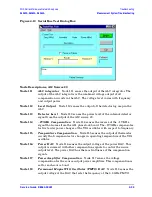
Figure 4-9 Typical Four Channel Display
• If all traces are present and are similar to the traces in
, then there are no
major problems with the analyzer’s measurement system. There may, however, be a
minor failure in the analyzer.
To test further:
— Go to
Chapter 3 , “Tests and Adjustments,”
and perform all the tests in that section.
— If a problem still exists, contact Agilent. Refer to
Summary of Contents for E8362A
Page 11: ...Service Guide E8364 90001 1 1 1 Safety and Regulatory Information ...
Page 19: ...Service Guide E8364 90001 2 1 2 General Product Information ...
Page 29: ...Service Guide E8364 90001 3 1 3 Tests and Adjustments ...
Page 79: ...Service Guide E8364 90001 4 1 4 Troubleshooting ...
Page 139: ...Service Guide E8364 90001 5 1 5 Theory of Operation ...
Page 169: ...Service Guide E8364 90001 6 1 6 Replaceable Parts ...
Page 215: ...Service Guide E8364 90001 7 1 7 Repair and Replacement Procedures ...
Page 287: ...Service Guide E8364 90001 A 1 A Error Terms ...
Page 303: ...Service Guide E8364 90001 B 1 B Option Enable Utility ...
Page 309: ...Service Guide E8364 90001 C 1 C Firmware Upgrades ...
Page 313: ...Service Guide E8364 90001 D 1 D Operating System Recovery ...

