background image

58

E5400-Pro Series Soft Touch User’s Guide

4

Operating the E5402A, E5405A, and E5406A-Pro Series Probes


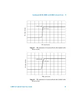
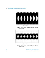
Figure 43

Logic analyzer eye opening for a PRBS signal of 500 mV p-p, 

1500 MT/s data rate

Figure 44

Logic analyzer eye opening for a PRBS signal of 200 mV p-p, 

1500 MT/s data rate

10

0

m

V per division

500 ps per division

10

0

m

V

 pe

r di

vi

sio

n

500 ps per division

Summary of Contents for E5386A

Page 1: ...A Agilent Technologies E5400 Pro Series Soft Touch Connectorless Probes User s Guide ...

Page 2: ...t shall control Technology Licenses The hardware and or software described in this document are furnished under a license and may be used or copied only in accor dance with the terms of such license Restricted Rights Legend If software is for use in the performance of a U S Government prime contract or subcon tract Software is delivered and licensed as Commercial computer software as defined in DF...

Page 3: ...es 34 channel Single ended Soft Touch Probe for analyzers with 40 pin cable connectors 15 The E5405A Pro Series 17 channel Differential Soft Touch Probe for analyzers with 90 pin cable connectors 16 The E5406A Pro Series 34 channel Single ended Soft Touch Probe for analyzers with 90 pin cable connectors 17 The E5386A Half channel Adapter for use with the 16760A logic analyzer 18 2 Mechanical Consi...

Page 4: ... Equivalent Probe Loads 42 Time Domain Transmission TDT 44 4 Operating the E5402A E5405A and E5406A Pro Series Probes Equivalent Probe Loads 48 Time Domain Transmission TDT 50 Step Inputs 53 Eye Opening 56 5 Circuit Board Design Transmission Line Considerations 60 Recommended Routing 61 Data and Clock Inputs per Operating Mode 63 Thresholds 66 E5404A pro series single ended soft touch probes 66 E5...

Page 5: ... s Guide 5 Half channel 1 25 and 1 5 Gb s modes 16760A only 68 6 Recommended Reading For More Information 70 MECL System Design Handbook 70 High speed Digital Design 70 Designing High speed Target Systems for Logic Analyzer Probing 70 ...

Page 6: ...6 E5400 Pro Series Soft Touch User s Guide ...

Page 7: ...eries Soft Touch Connectorless Probes User s Guide A 1 Overview Installation and Selection of Probing Options The E5400 Pro Series Soft Touch Probes at a Glance 8 Installation Instructions 10 Selection of Probing Options 12 ...

Page 8: ... Pro Series Differential E5404A Pro Series Single ended 40 pin LA cable E5406A Pro Series Single ended E5403A retention module 34 chan 90 pin LA cables 90 pin LA cables 16760A logic analyzer E5386A used with 16760A logic analyzer only E5402A E5405A E5406A Pro Series 90 pin LA cables E5412A right angle retention module 34 chan E5402A Pro Series Single ended ...

Page 9: ... right angle 34 channel single ended connectorless soft touch probe for analyzers with 90 pin cable connectors The E5404A pro series probe is a 34 channel single ended connectorless soft touch probe for analyzers with 40 pin cable connectors The E5405A pro series probe is a 17 channel differential connectorless soft touch probe for analyzers with 90 pin cable connectors The E5406A pro series probe...

Page 10: ...essary to clean the board and pins before soldering the retention module to the board 3 If your board has Organic Solder Preservative OSP finish apply solder paste to the footprint pads prior to reflow or hand soldering Typically dipped and coated finishes do not require extra solder paste 4 Attach the retention module to the board from either the top or bottom of the board Top side attach Can be ...

Page 11: ... into the board noting the keying pin b Solder the alignment pins to the back side of the board 5 Insert the probe into the retention module Ensure proper keying by aligning the Agilent logo on the probe with the one on the retention module and place the probe end into the retention module 6 Alternate turning each screw on the probe a little until both screws are finger tight like you would attach...

Page 12: ...probe and your logic analyzer module Table 1 Number of Probes Required Agi l entPr obe Agilent Logic Analyzer Module 16760A 16753A 16754A 16755A 16756A 16950A 1670 Series 34ch 1680 90Series 34ch 1670 Series 68ch 1680 90 Series 68ch 16715 16 17A 16740 41 42A 16750 51 52A B 16911A 1670 Series 102ch 1680 90 Series 102ch 16710 11 12A 16910A 1670 Series 136ch 1680 90Series 136ch E5402A right angle 34 c...

Page 13: ...ule 16760A 16753A 16754A 16755A 16756A 16950A 1670 Series 1680 90 Series 16710 11 12A 16715 16 17A 16740 41 4A 16750 51 52A B 16910A 16911A E5402A right angle 34 channel single ended soft touch probe 1 5 Gb s 800 Mb s n a n a E5404A 34 channel single ended soft touch probe n a n a 400 Mb s 500 Mb s E5405A 17 channel differential soft touch probe 1 5 Gb s 800 Mb s n a n a E5406A 34 channel single e...

Page 14: ...ers with signal amplitudes as small as 250 mV peak to peak A retention module must be installed on the target system board to attach the probe to the board There is a key on the retention module that indicates the egress of the cable when the probe is attached A kit of five retention modules are supplied with each probe Refer to Ordering retention modules on page 13 for information on ordering mor...

Page 15: ... state synchronous analysis clock rates of all the supported analyzers with signal amplitudes as small as 500 mV peak to peak A retention module must be installed on the target system board to attach the probe to the board A kit of five retention modules are supplied with each probe Refer to Ordering retention modules on page 13 for information on ordering more See Mechanical Considerations on pag...

Page 16: ...ntial signal amplitudes as small as 200 mV peak to peak A retention module must be installed on the target system board to attach the probe to the board A kit of five retention modules are supplied with each probe Refer to Ordering retention modules on page 13 for information on ordering more See Mechanical Considerations on page 19 for information on designing your target system board Figure 4 E5...

Page 17: ... state synchronous analysis clock rates of all the supported analyzers with signal amplitudes as small as 250 mV peak to peak A retention module must be installed on the target system board to attach the probe to the board A kit of five retention modules are supplied with each probe Refer to Ordering retention modules on page 13 for information on ordering more See Mechanical Considerations on pag...

Page 18: ...ly set thresholds to the proper values You need to go into the threshold menu and select differential custom or standard settings When using the adapter in half channel state mode Clock bits are not available in half channel state mode although JCLK on the master is still used Be sure to connect Master pod 1 of the logic analyzer to the upper bits 8 15 clk on the half channel adapter This is neces...

Page 19: ...bes User s Guide A 2 Mechanical Considerations Characteristics 20 Probe Dimensions 21 Board Layout Dimensions 25 Pin Outs for the Probes 28 E5386A Half channel Adapter Dimensions 36 Use the following mechanical information to design your target system board ...

Page 20: ... Considerations Characteristics Electrical considerations such as equivalent probe loads input impedance and time domain transmission are shown in chapters 3 and 4 of this manual Other characteristics are dependant on the logic analyzer module you are using ...

Page 21: ...ons 2 E5400 Pro Series Soft Touch User s Guide 21 Probe Dimensions The following figures show the dimensions of the Agilent E5400 pro series soft touch probes Figure 6 E5402A probe dimensions Top view E5402A Side view E5402A ...

Page 22: ...22 E5400 Pro Series Soft Touch User s Guide 2 Mechanical Considerations Figure 7 E5404A probe dimensions Top view E5404A Side view E5404A ...

Page 23: ...Mechanical Considerations 2 E5400 Pro Series Soft Touch User s Guide 23 Figure 8 E5405A probe dimensions Top view E5405A Side view E5405A ...

Page 24: ...24 E5400 Pro Series Soft Touch User s Guide 2 Mechanical Considerations Figure 9 E5406A probe dimensions Top view E5406A Side view E5406A ...

Page 25: ...de 25 Board Layout Dimensions Use the following dimensions to layout your PC board pads and holes for use with the soft touch probes Retention Module Dimensions Figure 10 E5403A retention module dimensions Figure 11 E5412A retention module dimensions 0 158 in 4 01 mm ...

Page 26: ...ons Figure 12 E5403A side by side dimensions Optimal board thickness for this top side mount retention module is shown above Retention modules can be hand soldered into thicker boards but will not form a bottom side solder fillet Figure 13 E5412A side by side dimensions ...

Page 27: ... 27 Footprint Dimensions The retention module alignment is symetrical around the pad footprint Figure 14 Top view footprint dimensions drawing notes next page A1 A27 B1 B27 A1 A27 B1 B27 NOTE The above view is looking down onto the footprint on the printed circuit board ...

Page 28: ...ined 3 Surface finishes on pads should be HASL immersion silver or gold over nickel 4 This footprint is compatible with retention module Agilent model number E5403A 5 Plated through hole should not be tied to ground plane for thermal relief VIA Pad NOTE If you will be using the soft touch probes with a 16900 series logic analyzer running V2 5 or higher probe types can be defined in XML configurati...

Page 29: ... footprint then A8 and B20 are unused They can be grounded not connected left floating or driven These pads are not probed with the E5404A probe A1 A2 A3 A4 A5 A6 A7 A8 A9 A10 A11 A12 A13 A14 A15 A16 A17 A18 A19 A20 A21 A22 A23 A24 A25 A26 A27 D0 D1 GND D4 D5 GND CK 1 GND D10 D11 GND D14 D15 GND D2 D3 GND D6 D7 GND D8 D9 GND D12 D13 GND GND D2 D3 GND D6 D7 GND D8 D9 GND D12 D13 GND D0 D1 GND D4 D5...

Page 30: ...where CK1 and CK2 are driven in the E5406A probe Grounding these pads will allow the user defined threshold in the analyzer to be used as in normal single ended operation If you are using differential clocks route the Odd pod clock such that the positive side of the pair goes to A7 CK1 and the negative side of the pair goes to A8 CK1 Similarily route the Even pod clock such that the positive side ...

Page 31: ...D6 B5 6 Ground A6 D7 B6 7 Clock 1 A7 Clock Ground B7 GND NC Clock 1 A8 See pg 29 D8 B8 8 Ground A9 D9 B9 9 D10 A10 10 Ground B10 D11 A11 11 D12 B11 12 Ground A12 D13 B12 13 D14 A13 14 Ground B13 D15 A14 15 D0 B14 0 Whichever pod is connected to Even on the E5404A probe Ground A15 Whichever pod is connected to Even on the E5404A probe D1 B15 1 D2 A16 2 Ground B16 D3 A17 3 D4 B17 4 Ground A18 D5 B18...

Page 32: ...rs Figure 16 Pad numbers for E5405A pro series A1 A2 A3 A4 A5 A6 A7 A8 A9 A10 A11 A12 A13 A14 A15 A16 A17 A18 A19 A20 A21 A22 A23 A24 A25 A26 A27 D0 D0 GND D2 D2 GND D4 D4 GND D6 D6 GND NC NC GND D8 D8 GND D10 D10 GND D12 D12 GND D14 D14 GND GND D1 D1 GND D3 D3 GND D5 D5 GND D7 D7 GND CLK CLK GND D9 D9 GND D11 D11 GND D13 D13 GND D15 D15 B1 B2 B3 B4 B5 B6 B7 B8 B9 B10 B11 B12 B13 B14 B15 B16 B17 B...

Page 33: ...ged into the E5405A probe D0 A2 D1 B2 Ground A3 D1 B3 1 D2 A4 2 Ground B4 D2 A5 D3 B5 Ground A6 D3 B6 3 D4 A7 4 Ground B7 D4 A8 D5 B8 Ground A9 D5 B9 5 D6 A10 6 Ground B10 D6 A11 D7 B11 Ground A12 D7 B12 7 NC A13 Ground B13 NC A14 Clock B14 GND A15 Clock B15 Clock D8 A16 8 Ground B16 D8 A17 D9 B17 Ground A18 D9 B18 9 D10 A19 10 Ground B19 D10 A20 D11 B20 Ground A21 D11 B21 11 D12 A22 12 Ground B22...

Page 34: ...or E5402 E5406A pro series A1 A2 A3 A4 A5 A6 A7 A8 A9 A10 A11 A12 A13 A14 A15 A16 A17 A18 A19 A20 A21 A22 A23 A24 A25 A26 A27 D0 D1 GND D4 D5 GND CK 1 GND CK1 GND D10 D11 GND D14 D15 GND D2 D3 GND D6 D7 GND D8 D9 GND D12 D13 GND GND D2 D3 GND D6 D7 GND D8 D9 GND D12 D13 GND D0 D1 GND D4 D5 GND GND CK 2 CK 2 GND D10 D11 GND D14 D15 B1 B2 B3 B4 B5 B6 B7 B8 B9 B10 B11 B12 B13 B14 B15 B16 B17 B18 B19 ...

Page 35: ...d B4 D5 A5 5 D6 B5 6 Ground A6 D7 B6 7 Clock 1 A7 Clock Ground B7 GND Clock 1 A8 Clock D8 B8 8 Ground A9 D9 B9 9 D10 A10 10 Ground B10 D11 A11 11 D12 B11 12 Ground A12 D13 B12 13 D14 A13 14 Ground B13 D15 A14 15 D0 B14 0 Whichever pod is connected to Even on the E5402A E5406A probe Ground A15 Whichever pod is connected to Even on the E5402A E5406A probe D1 B15 1 D2 A16 2 Ground B16 D3 A17 3 D4 B17...

Page 36: ...ies Soft Touch User s Guide 2 Mechanical Considerations E5386A Half channel Adapter Dimensions The E5386A half channel adapter works with the 16760A logic analyzer and the soft touch probes Figure 18 E5386A dimensions ...

Page 37: ...ignments Figure 19 Half channel adapter with E5405A pro series Table 4 Pin out table for E5386A connected to an E5405A Logic analyzer pods 16760A only E5386A half channel adapter E5405A differential probe E5405A Differential Probe Negative Signals Positive Signals Logic Analyzer Signal Name Pin Signal Name Pin Channel Pod D0 A2 D0 A1 0 Whichever pod is plugged into bits 0 7 D1 B2 D1 B3 2 D2 A5 D2 ...

Page 38: ... adapters with E5402A E5406A pro series D8 A17 D8 A16 0 Whichever pod is plugged into bits 8 15 D9 B17 D9 B18 2 D10 A20 D10 A19 4 D011 B20 D11 B21 6 D12 A23 D12 A22 8 D13 B23 D13 B24 10 D14 A26 D14 A25 12 D15 B26 D15 B27 14 D16 Clk B14 D16 Clk B15 Clock E5405A Differential Probe Negative Signals Positive Signals Logic Analyzer Signal Name Pin Signal Name Pin Channel Pod Logic analyzer pods 16760 o...

Page 39: ... pod is connectedto bits 0 7 on the odd E5386A D0 B14 0 Whichever pod is connectedto bits 0 7 on the even E5386A D1 A2 2 D1 B15 2 D2 B2 4 D2 A16 4 D3 B3 6 D3 A17 6 D4 A4 8 D4 B17 8 D5 A5 10 D5 B18 10 D6 B5 12 D6 A19 12 D7 B6 14 D7 A20 14 D8 B8 0 Whichever pod is connectedto bits 8 15 on the odd E5386A D8 A22 0 Whichever pod is connectedto bits 8 15 on the even E5386A D9 B9 2 D9 A23 2 D10 A10 4 D10...

Page 40: ...40 E5400 Pro Series Soft Touch User s Guide 2 Mechanical Considerations ...

Page 41: ...Connectorless Probes User s Guide A 3 Operating the E5404A Pro Series Probes Equivalent Probe Loads 42 Time Domain Transmission TDT 44 Electrical considerations such as equivalent probe loads input impedance and time domain transmission TDT ...

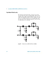
Page 42: ...ly models the probe load out to 6 GHz The figure on the following page shows the agreement between measured impedance and this model Figure 21 Probe load models E5404A 400Ω Rtap Cstub 0 375pF Rtip 100kΩ Din Ctip 10pF 250Ω Rtip1 1 17nH Lspring2 0 63nH Lspring1 Cstub 0 375pF Rgnd1 10Ω Ccoupling 0 070pF Rtip2 100kΩ Din Ctip 10pF Rgnd2 120Ω Complex Includes capacitive coupling between channels and ind...

Page 43: ...de 43 Figure 22 Measured versus modeled input impedance E5404A 1 8 6 10 5 4 2 1 8 6 4 2 Ohms 10 Frequency 6 8 1 2 4 7 9 3 5 6 8 1 2 4 7 9 3 5 6 8 1 2 4 7 9 3 5 6 8 1 2 4 7 9 3 5 6 8 1 2 4 7 9 3 5 6 Modeled complex 1 8 6 4 2 1 8 6 4 Modeled simple Measured 100 k 1 M 10 M 100 M 1 G ...

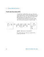
Page 44: ...easurements are useful for understanding the probe loading effects as seen at the target receiver The following TDT measurements were made mid bus on a 50Ω transmission line load terminated at the receiver These measurements show how the soft touch probes affect an ideal step seen by the receiver for various rise times Figure 23 TDT measurement schematic E5404A The following plots were made on an ...

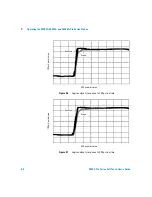
Page 45: ...24 TDT measurement at receiver with and without probe load for 150 ps rise time Figure 25 TDT measurement at receiver with and without probe load for 250 ps rise time 50 mV per division 500 ps per division with probe without probe 50 mV per division 500 ps per division with probe without probe ...
Page 46: ...6 TDT measurement at receiver with and without probe load for 500 ps rise time Figure 27 TDT measurement at receiver with and without probe load for 1000 ps rise time 50 mV per division 500 ps per division with probe without probe 50 mV per division 500 ps per division with probe without probe ...
Page 47: ...4 Operating the E5402A E5405A and E5406A Pro Series Probes Equivalent Probe Loads 48 Time Domain Transmission TDT 50 Step Inputs 53 Eye Opening 56 Electrical considerations such as equivalent probe loads input impedance time domain transmission TDT step inputs and eye opening ...

Page 48: ...DR TDT using a 50 Ω test fixture The following schematic accurately models the probe load out to 6 GHz The figure on the following page shows the agreement between measured impedance and this model PC board pads are not included Figure 28 Probe load model E5402A E5405A and E5406A 20KΩ Rtip1 1 17nH L12 0 63nH L11 C12 0 280pF Rgnd1 0 5Ω Cm12 0 070pF Rtrm1 75Ω 350pF Cshnt1 20KΩ Rtip2 1 17nH L22 0 63n...

Page 49: ...ouch User s Guide 49 Figure 29 Measured versus modeled input impedance E5402A E5404A and E5406A 2 1 8 6 10 4 4 2 1 8 6 4 2 1 8 6 4 2 Ohms 10 1 100 k Frequency 6 8 1 2 4 7 9 3 5 6 8 1 2 4 7 9 3 5 6 8 1 2 4 7 9 3 5 6 8 1 2 4 7 9 3 5 6 8 1 2 4 7 9 3 5 6 Measured Model 1 M 10 M 100 M 1 G ...

Page 50: ...eful for understanding the probe loading effects as seen at the target receiver The following TDT measurements were made mid bus on a 50Ω transmission line load terminated at the receiver These measurements show how the E5402A E5405A and E5406A pro series soft touch probes affect an ideal step seen by the receiver for various rise times Figure 30 TDT measurement schematic E5402A E5405A and E5406A ...

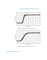
Page 51: ...1 Figure 31 TDT measurement at receiver with and without probe load for 100 ps rise time Figure 32 TDT measurement at receiver with and without probe load for 250 ps rise time 50 mV per division 500 ps per division with probe without probe 50 mV per division 500 ps per division with probe without probe ...

Page 52: ... Figure 33 TDT measurement at receiver with and without probe load for 500 ps rise time Figure 34 TDT measurement at receiver with and without probe load for 1000 ps rise time 50 mV per division 500 ps per division with probe without probe 50 mV per division 500 ps per division with probe without probe ...

Page 53: ...the logic analyzer The measurements were made on a mid bus connection to a 50Ω transmission line load terminated at the receiver These measurements show the logic analyzer s response while using the E5402A E5405A and E5406A pro series soft touch probes Figure 35 Step input measurement schematic E5402A E5405A and E5406A The following plots were made on an Agilent 54750A oscilloscope and an Agilent ...

Page 54: ...E5402A E5405A and E5406A Pro Series Probes Figure 36 Logic analyzer s response to 150 ps rise time Figure 37 Logic analyzer s response to 250 ps rise time 100 mV per division 500 ps per division Scope EyeScan 100 mV per division 500 ps per division Scope EyeScan ...



Page 55: ...400 Pro Series Soft Touch User s Guide 55 Figure 38 Logic analyzer s response to 500 ps rise time Figure 39 Logic analyzer s response to 1000 ps rise time 100 mV per division 500 ps per division Scope EyeScan 100 mV per division 500 ps per division Scope EyeScan ...

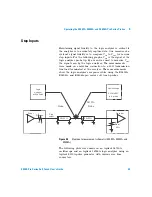
Page 56: ...he eye opening seen by the logic analyzer The following eye diagrams were measured using E5402A E5405A and E5406A pro series soft touch probes and Eye Scan while probed mid bus on a 50Ω transmission line load terminated at the receiver The data patterns were generated using a 223 1 pseudo random bit sequence PRBS Figure 40 Eye opening measurement schematic E5402 05 06A The following plots were mad...

Page 57: ...t Touch User s Guide 57 Figure 41 Logic analyzer eye opening for a PRBS signal of 500 mV p p 800 MT s data rate Figure 42 Logic analyzer eye opening for a PRBS signal of 500 mV p p 1250 MT s data rate 100 mV per division 500 ps per division 100 mV per division 500 ps per division ...

Page 58: ...5406A Pro Series Probes Figure 43 Logic analyzer eye opening for a PRBS signal of 500 mV p p 1500 MT s data rate Figure 44 Logic analyzer eye opening for a PRBS signal of 200 mV p p 1500 MT s data rate 100 mV per division 500 ps per division 100 mV per division 500 ps per division ...

Page 59: ...ss Probes User s Guide A 5 Circuit Board Design Transmission Line Considerations 60 Recommended Routing 61 Data and Clock Inputs per Operating Mode 63 Thresholds 66 Signal Access 67 Design considerations when you layout your circuit board ...

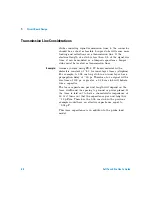
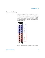
Page 60: ...terial with a dielectric constant of 4 3 for inner layer traces stripline For example A 0 28 cm long stub in an inner layer has a propagation delay of 20 ps Therefore for a signal with a rise time of 100 ps or greater a 0 28 cm stub will behave like a capacitor The trace capacitance per unit length will depend on the trace width and the spacing to ground or power planes If the trace is laid out to...

Page 61: ...make a good electrical connection with a small amount of compression force on a choice of standard PCB platings Additionally the pin contact points are free from the contamination effects that plague other connector less probing technologies Figure 45 34 bit single ended routing E5402A E5404A and E5406A D0 B1 A1 B27 A27 D1 D2 D3 D4 D5 D6 D7 CK1 CK1 D8 D9 D10 D11 D12 D13 D14 D15 ODD POD EVEN POD D0...

Page 62: ...62 Soft Touch Pro User s Guide 5 Circuit Board Design Figure 46 17 bit differential routing E5405A B1 A1 B27 A27 D0 D1 D2 D3 D4 D5 D6 D7 D8 D9 D10 D11 D12 D13 D14 D15 CK ...

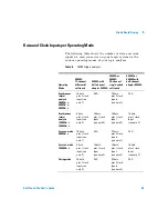
Page 63: ...e analysis 200 Mb s 400 Mb s 800 Mb s 16 data plus 1 clock input see note 1 N A 32 data plus 2 clock inputs see note 1 N A Synchronous state analysis 1250 Mb s 1500 Mb s 8 data plus 1 clock input see note 2 16 data plus 1 clock input see note 2 16 data plus 1 clock input see note 2 16 data plus 1 clock input see note 2 Eye scan mode 800 Mb s 16 data plus 1 clock input see note 1 N A 32 data plus 2...

Page 64: ...igned to labels To realize 17 data inputs in full channel mode while using time tags in addition to a clock input on a single 16760A module or on the master module in a multi card set you must route the data signals to pod 2 and the clock to pod 1 A convenient way to avoid laying out a second connector to connect only the clock signal is to use the Agilent E5382A flying lead set to make the connec...

Page 65: ...the master module in a multi card set The clock inputs on the other pods can be assigned to labels and acquired as data inputs Operating Mode E5405A 17 channel differential soft touch E5402A or E5406A 34 channel single ended soft touch Synchronous state analysis 300 Mb s 800 Mb s 16 data plus 1 clock input see note 1 32 data plus 2 clock inputs see note 1 Eye scan mode 300 Mb s 600 Mb s 16 data pl...

Page 66: ...e crossover of the data and data inputs You may also use the E5405A differential probe to acquire single ended signals If you are using the E5405A probe to acquire single ended signals you should either ground the data inputs or connect them to a dc power supply You may Ground the data inputs and adjust the threshold in the user interface Or Supply a threshold reference voltage to the data inputs ...

Page 67: ...nal the clock input should be either grounded or connected to a dc power supply You may Ground the clock input and adjust the clock threshold from the user interface to between 3V dc and 5V dc Signal Access Labels split across probes If a label is split across more than one pod this leads to restrictions in triggering Refer to Triggering with the Agilent 1675x and 1676x Agilent publication number ...

Page 68: ...es only the even channels 0 2 4 etc In the Format user interface only the even data bits will be connected to the analyzer Note that in the 1 25 and 1 5 Gb s half channel mode the clock inputs cannot be assigned as bits in a label E5386A Half channel Adapter The E5386A can be used with the E5405A pro series differential soft touch probe or the E5402A E5406A pro series single ended probes to map th...

Page 69: ...ent E5400 Pro Series Soft Touch Connectorless Probes User s Guide A 6 Recommended Reading For More Information 70 A list of recommended reading for more information about systems and high speed digital design ...

Page 70: ...ed by Motorola This handbook can be obtained from ON Semiconductor on the web Go to http onsemi com Click on On line ordering under Documentation Click on the link General search Type in HB205 in the Document number field Click Submit To view the document online click on PDF in the right hand column titled PDF MFAX Or order a hardcopy of the handbook on line High speed Digital Design Johnson Howar...

Page 71: ...r fire hazard If you energize this instrument by an auto transformer for voltage reduction or mains isolation the common terminal must be connected to the earth terminal of the power source Whenever it is likely that the ground protection is impaired you must make the instru ment inoperative and secure it against any unintended operation Service instructions are for trained service personnel To av...

Page 72: ...ual symbol the product is marked with this symbol when it is necessary for you to refer to the instruction manual in order to protect against damage to the prod uct Hazardous voltage symbol Earth terminal symbol Used to indicate a circuit common connected to grounded chassis ...

Page 73: ... footprint 27 retention module 25 E E5386A half channel adapter 18 E5404A 34 chan single ended 14 15 E5405A 17 chan differential 16 E5406A 34 chan single ended 17 equivalent probe loads E5404A 42 E5405A 48 E5406A 48 eye opening 56 eye scan 63 F footprint dimensions 27 H half channel adapter 18 half channel mode 68 high speed digital design 70 target system design 70 I input amplitude 16 installati...

Page 74: ...taching 10 dimensions 25 ordering 13 routing 61 S safety symbols 72 selecting a probe 12 signal access 67 single ended probe E5405A 14 15 E5406A 17 solder retention module 11 state speed 13 step inputs 53 synchronous state analysis 63 T thresholds 66 time domain transmission 50 E5404A 44 top side attach 10 transmission line considerations 60 triggering 67 ...

Reviews: