


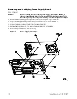


Installation Note E4411–90047
13
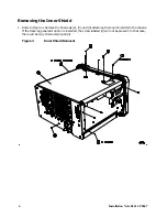
Replacing the Outer Case
1. Replace the instrument outer case by matching the grill on the side of the case to the fan on the
power supply assembly.
2. Fit the leading edge of the case completely into the slot on the back of the front frame assembly.
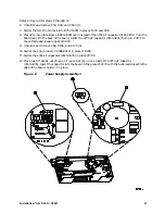
Refer to Figure 2 for steps 3 through 5.
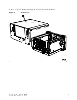
3. Replace the rear frame assembly (2) on the instrument.
NOTE
The Rear EMI Gasket (3) that clips onto the rear panel can come loose. When
replacing the outer case, make sure the gasket is in the correct position.
In some cases, the Rear EMI Gasket may be misaligned, or the fingers may not be
bent far enough to make proper contact. Poor contact will negatively impact the
EMI performance of the instrument.
4. Check to make sure that all fingers of the Rear EMI Gasket (3) contact the rear panels of the
boards/blank panels. Each pair of fingers should contact the faceplate to its left and right,
respectively.
If the contacts of the Rear EMI Gasket are misaligned, remove the rear frame, loosen all the rear
card cage screws, power supply screw, IF screws, and option card screws, and move the whole group
of parts in the direction needed to ensure that the fingers of the gasket make contact with the rear
panels.
If the panels are properly aligned, but the EMI fingers do not reach the panels, remove the rear
frame and bend the fingers farther out to ensure that they make contact with the rear panels.
5. Use the four screws (1) to fasten the rear frame to the instrument. Torque to 247 N/cm (21-inch
pounds).
6. Using a pen with indelible ink, write the following on the E4411A serial number label, located at
the lower right side of the rear panel:
SN E4411A-09 Installed
.
After a Spectrum Analyzer Repair
A High Pot Test—also known as High Potential or Dielectric Withstand Test—is required after working
on the high voltage section of the power supply. In addition, after the spectrum analyzer power supply
has been upgraded, perform the related adjustments and performance verification tests. Refer to
Table 5-2 in Chapter 5 of the ESA-L1500A Spectrum Analyzer Service Guide for the related
adjustments and performance verification tests required for the A5 power supply assembly.


