Agilent Technologies CrossLab RapidFire 400 Installation Checklist Download Page 10

Instrument Installation Checklist 

Revision: 

A.00

, Issued: 

January


17

, 20

21


Document part number: 

D0007550


Page    ____    of    ____      

 
© Agilent Technologies, Inc. 20

21


d


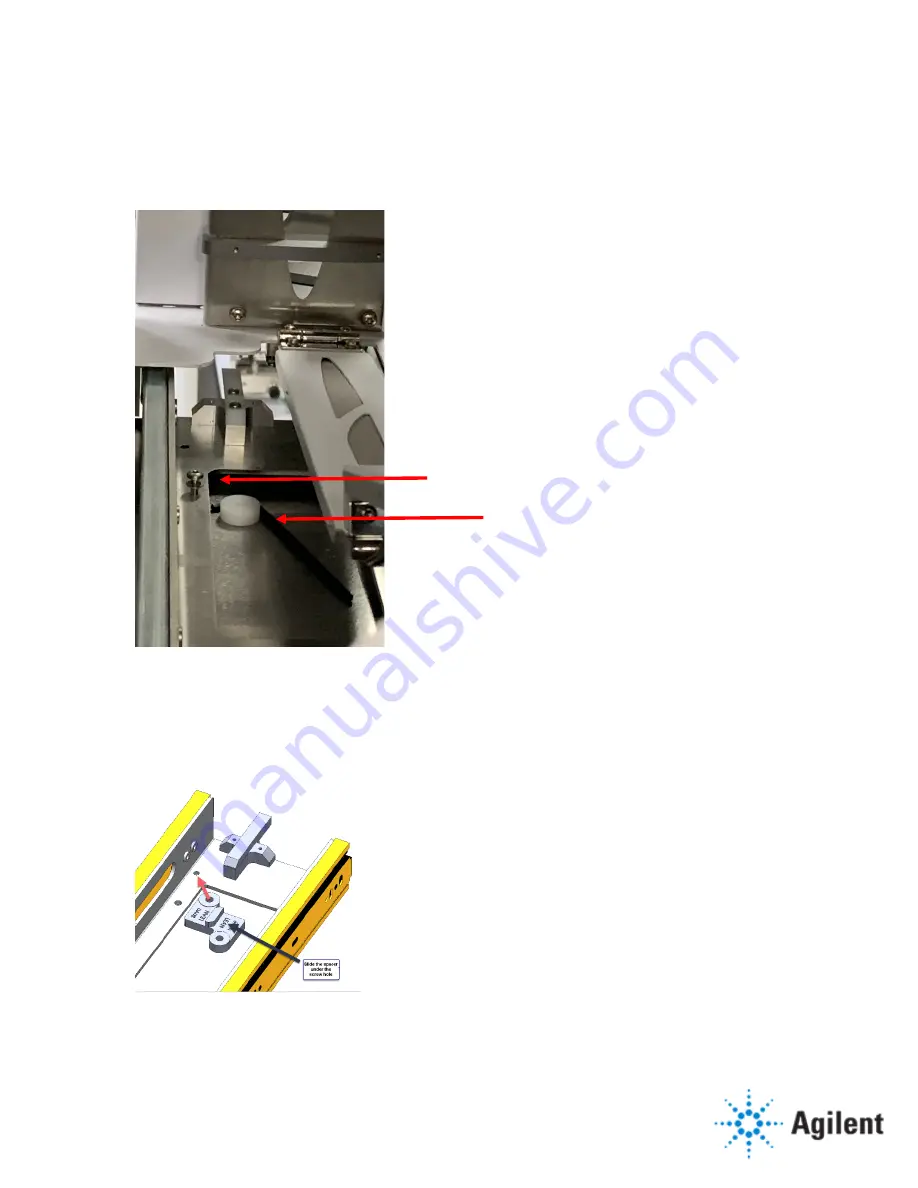
To increase the gap by 3-mm, turn the adjuster screw (

1

) three turns (six turns for a 6-mm 

gap) and remove the existing O-ring and O-ring cup by corralling the cup with the L of a 

hex wrench (

2

). 

Figure 5 Adjuster screw and O-ring cup on the front-right side, viewed from the rear 


e


Slide the lean correction spacer under the mounting plate, ensuring that the 3-mm (or 

6-mm, if using) correction side is under the mounting plate. When the tab on the spacer is 

biased against the cutout on the mounting plate, the spacer hole and the mounting plate 

hole will be aligned. 

Figure 6 Positioning correction spacer under the mounting plate 


1


2


Summary of Contents for CrossLab RapidFire 400

Page 1: ...tomer representative should be available to the engineer while performing the installation Some installation tasks will be beneficial to you if you are present refer to sections in this checklist Important Customer Web Links Videos about specific preparation requirements for your instrument can be found by searching the Agilent YouTube channel at https www youtube com user agilent To access Agilen...

Page 2: ... relevant information Complete the relevant checkboxes in the checklist using a X or tick mark Check Section not applicable check boxes to indicate services tasks not delivered as appropriate Complete the Service Review section together with the customer Complete the fields for page numbers at the foot of each selected page Complete the total number of pages field in the Service Completion section...

Page 3: ...his box if an instrument configuration report is attached instead of completing the table Instrument System Name and ID Instrument System Site and Location List System Component Product Numbers List the Serial Numbers of each Component 1 2 3 4 5 6 7 8 9 10 Preparation Unpack verify the condition and completeness of shipment For discrepancies use the following table Product or Part Description Obse...

Page 4: ...omer that instrument control settings data methods etc have been properly saved or archived before starting any installation procedures Obtain the sample plates the customer will be using Installation Procedure Unpacking and inventorying the shipped contents Section not applicable Unpack and inspect the components for the temperature control unit You should have the following items Chiller control...

Page 5: ...ting plate Set the cover and fasteners aside for reinstallation later 5 Feed the ribbon cables up through the access hole in the deck and tie the ribbon cables and the cable arm to the rear elevator stack using the long cable ties included in the installation kit such that the cable arm bracket is tucked out of the way when the drawer is opened 6 Using a T 20 driver remove the drawer handle Set th...

Page 6: ...ides lift the unit and place it on the deck centering it left and right in the cutout on the base plate The front edge of the enclosure should align with the front edge of the base plate 4 Remove the plastic sheet 5 Align all four enclosure mounting holes with the threaded holes in the base plate a Start by inserting a thin hex wrench into the holes Figure 1 Aligning enclosure box mounting holes b...

Page 7: ...les in the enclosure and base plate b Using a 3 mm hex wrench tighten the screws until you feel a hard stop c With the slides in their closed position pull the bearing retainers forward in the slides of the elevator mounting plate d Lift the drawer and align the lead ins on the drawer and the mounted slides in the enclosure and slide the drawer most of the way in e From the opening in the back of ...

Page 8: ...Determine which correction size spacer to use If the drawer tilt is 3 5 mm use the 3 mm side of the correction spacers If the drawer tilt is 5 mm use the 6 mm side of the correction spacers 2 Determine which side of the enclosure to insert the spacers If the drawer leans to the left the gap is smaller at the top on the left side as you face the front of the enclosure you will replace the left two ...

Page 9: ...enough to access the front mounting screws and from the opening in the rear remove the left or right front screw depending on which way the drawer is leaning see previous step c Insert the adjuster screw in the adjustment hole located near the mounting hole and tighten the screw until it touches the plate underneath Figure 4 Adjustment hole for the right front mount ...

Page 10: ...up by corralling the cup with the L of a hex wrench 2 Figure 5 Adjuster screw and O ring cup on the front right side viewed from the rear e Slide the lean correction spacer under the mounting plate ensuring that the 3 mm or 6 mm if using correction side is under the mounting plate When the tab on the spacer is biased against the cutout on the mounting plate the spacer hole and the mounting plate h...

Page 11: ...rection spacer Note The weight of the drawer should be enough to lift up the mounting plate so you don t have to use the adjuster to remove the rear O ring and O ring cup i Replace the mounting screw j Verify the change in tilt by checking the elevator to enclosure wall clearance Routing and connecting the enclosure cables 1 Feed the ribbon cables and temperature sensor cable through the cable por...

Page 12: ... below Figure 9 Path of the ribbon cable coming from enclosure door 5 Take the piece of foam from the installation kit make an M with the foam and sandwich all the cables from the interior of the enclosure into the M 6 Stuff the foam sandwich into the enclosure cable pass through hole until it is flush with the edge Inserting the foam causes some of the cable to be pushed back into the enclosure C...

Page 13: ...a T 10 driver and M3 x 10 mm screws P N 0515 1103 9 Attach the ferrites at the indicated location on the ribbon cables Figure 11 Attaching ferrite to ribbon cable 10 Connect the four ribbon cables to the robot elevator control box Figure 12 Elevator cable connections to the control box 11 Install the auxiliary drain tube P N G9532 60110 a Locate the drainpipe exiting below the deck underneath the ...

Page 14: ...he TEC and insert it into the mounting hole with the cables exiting the top Downward pressure may need to be applied to compress the seal at the base of the mounting hole CAUTION The TEC MUST be installed such that the side with the terminal block is in the top position or water will leak onto the electronics below 2 Secure the TEC to the back of the enclosure using six M 4 x 10 mm pan head screws...

Page 15: ...les inserted in the TEC cover 5 Connect the TEC cable wires to the terminal block a Using a thin blade screwdriver Insert the screwdriver into the small hole above where you want to insert the wire b Depress the metal contact c Insert the wire and release the screwdriver Figure 16 Inserting cable wires into the terminal block on the TEC Use the following table as a guide to map the wires Cable wir...

Page 16: ...er small red 6 Route the TEC cable around the fan and place the cover over the TEC 7 Attach the cover with four screws P N 0515 0430 and a T 10 driver two on the top of the cover and two on the bottom 8 Route the TEC cable through the deck pass through Installing the condensation pump 1 Using a T 10 driver partially install two M3 x 40 mm mounting screws into the holes for the pump located on the ...

Page 17: ... underneath the deck and feed the drain tube through the deck pass through CAUTION As the drain tube passes over the plastic barrier it must be clipped to an elevation higher than the pump connection to prevent dripping onto the electronics in the event of a pump leak 4 Feed the tube through the hole in the drain tube guide P N G9532 20141 5 Slide the end of the pump drain tube over the drainpipe ...

Page 18: ...densation pump labeled Pump Temperature sensor Serial on the controller to USB on the computer P N 8121 2109 Connect the power cable to the upper power strip Turn on the TEC controller power switch located above the power cord connection Secure the TEC controller to the frame with M5 screws P N 0515 0387 and a T 25 driver Installing the front door to the enclosure 1 Pull out the drawer and partial...

Page 19: ... corresponding slots in the door Figure 21 Placing the cutouts on the door over the partially installed screws 3 While the door is hanging on the partially threaded screws attach the other six M4 x 8 mm screws 4 Adjust the door skew a Loosen the six flat head screws on the door face using a T 20 driver b Position rotate the front face until it is aligned to the front of the enclosure and tighten t...

Page 20: ...s the drawer closes 7 Hold the door shut against the enclosure and tighten the two visible screws on each side 8 Open the drawer and tighten the remaining screws that hold the door to the enclosure drawer 9 Remove the jigs close the door and verify the door is aligned and that the door seals are contacting the enclosure sealing face 10 Attach the handle to the side of the door with two M4 x 18 mm ...

Page 21: ...the controller USB cable back into the computer and close the control panel 2 Configure the cooling unit in the RapidFire software a Open the PlateHandler cfg file C Agilent RapidFire Config Files for RF400 in a text editor b Change GEMINI_RF_ROBOT_HAS_CHILLER_DOOR 0 to 1 c Change CHILLER_COM_PORT NOCOM to X where X is the number you determined in step 1 d Save and close the file 3 Start the Rapid...

Page 22: ...Lower plate elevators for loading c Click System Tools Robot BCR teachpoint d Click Yes to home the chiller door if applicable BCR stage and elevators e In the teaching dialog box select Front Stack and move the elevator of the front stack up to 250 mm f If there is a chiller door in the Chiller Door area click Open to open the enclosure door g Move the robot up in the z direction using the 3 0 mm...

Page 23: ...f the front stack j Install the stacker jig on top of the front stack k Slide the drawer back into the instrument or enclosure if there is a cooling unit plug the camera into a USB port on the computer and open the camera application in Windows l Using the 3 mm hex wrench move the robot in the z axis up until the grippers are above the stacker jig m Manually move the robot in the y axis to the fro...

Page 24: ... Setting the y and theta axes teachpoints for the stacks 1 Ensure the elevators for all three stacks are at 250 mm 2 Ensure the gripper jig is installed and stacker jig is handy 3 Set the theta and y axes a Place the camera on the elevator of the front stack and the stacker jig on the top of the stack b Slide the drawer back in and observe the jigs through the camera application c Adjust the robot...

Page 25: ...stall the jig into the robot gripper b Using the commands in the teachpoint dialog box move all the elevator stages to their teach height c Manually move the robot in the z axis direction into the elevator stage area well above the upper limit of the elevator stage If you have a temperature control unit move the robot into the enclosure door area at a safe height above the elevator stage d Move th...

Page 26: ...ion in very small increments until the light on the stage jig flickers on and off observing from the outside with the doors still closed When the jig is in the correct position click Set Z teachpoint coord in the teaching dialog box Select Middle Stack from the Robot Teachpoint list and repeat this procedure Select Rear Stack from the Robot Teachpoint list and repeat this procedure Setting the tea...

Page 27: ... adjust the robot in the y axis to fit the jig into the BCR stage c Securely nest the jig into the BCR stage d Close the doors and engage the axes motors e Set the robot teachpoint for the barcode reader stage Select Barcode from the Robot Teachpoint list Click Teach at current Y Z Theta f Set the barcode reader teachpoint Select Barcode from the Robot Teachpoint list In the Barcode Reader area cl...

Page 28: ...osition for the plate handler c Disable the robot motors and ensure the stage jig is correctly installed in the robot grippers d Move the robot so that the jig rests on the plate stage Make sure it is flat and snug against the side that holds the matrix bottles You might have to move the x axis of the stage so that the jig is against the side that holds the matrix bottles If you do move the x axis...

Page 29: ...se the RapidFire software d Open the RapidFire cfg file in Notepad and change CONFIGURE_BENCHBOT 0 4 Save and close the file and restart the RapidFire software Verifying the system operation 1 Set the temperature to 3 C and load the stacks with some plates of the type the customer is using 2 Verify the enclosure has cooled 3 Run a batch file that uses the stacker and barcode reader 4 Ensure the ro...

Page 30: ...Page ____ of ____ Agilent Technologies Inc 2021 Installation checkout customer present Section not applicable Show the customer the changes to the system hardware and software Show the customer how to operate the system with the cooling unit in place Repeat the system verification runs for the customer ...

Page 31: ...de with the customer Explain Agilent warranty for instruments Explain how to use manuals guides and online help Explain how to get self help and FAQs online Explain how to log an instrument service call and support services that are available Advise customer of additional instrument training options If the instrument firmware was updated record the details of the change in the service engineer s c...

Page 32: ... 00 Issued January 17 2021 Document part number D0007550 Page ____ of ____ Agilent Technologies Inc 2021 Service Completion Service request number Date service completed Agilent signature Customer signature Total number of pages in this document ...

Reviews: