background image

Installing the 81150A/81160A 


2.1


The Front Panel 


Introduction 

The instrument is mainly operated from the front panel, when used for 
bench top testing.  
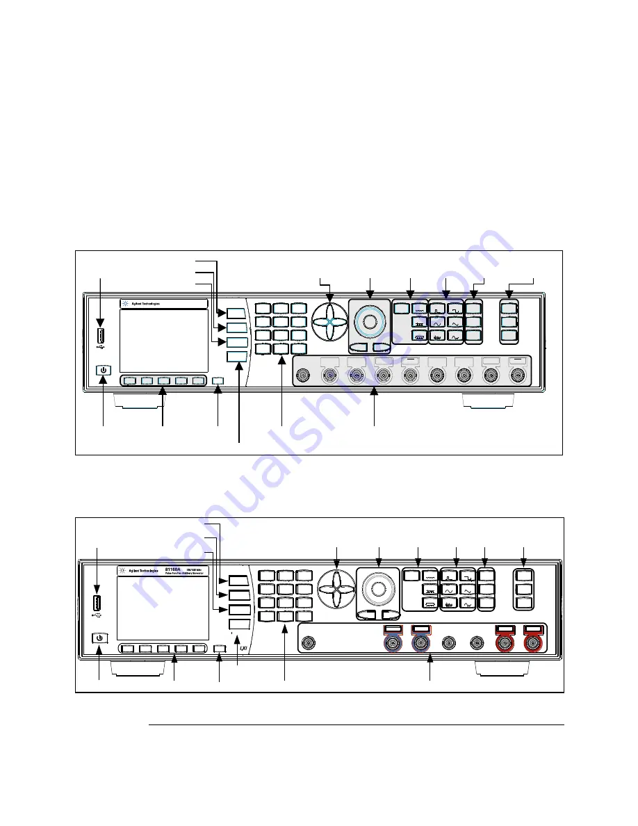
Now that you have unpacked the instrument and plugged it in, let us take a 
look at the main elements of the Front Panel. These are shown and 
explained in brief below.  


Ch 1

Ch 2

Coupling

Graph

Cancel

7

8

9

4

5

6

1

2

3

0

.

+/-

Out 2

Out 2

Out 1

Out 1

Man

Cont

Pulse

Square

Mod

Store/

Recall

Utility

Help

Sweep

Burst

Arb

Ramp

Noise

Sine

Trig

Gated

max. ±15V

Trigger Out 2

Strobe Out 2

External In

Trigger Out 1

Strobe Out 1

81150A

Pulse Function Arbitrary Generator

120 MHz

Local

Power Switch

Menu Softkeys

Cancel

Graph / Local

Numeric Keypad

Inputs / Outputs

USB Host

Channel 1 Selection

Channel Coupling

Channel 2 Selection

Navigation

Keys

Rotary Knob

 Cursor Keys

Trigger

Modes

Waveform

Type

Advanced

Modes

Special

Function Keys


Front-panel of the 81150A 


Ch 1

Ch 2

Coupli ng

Gr aph

Ca n c e l

L o c a l

m a x .   ± 1 0 V

E x t e r n a l   I n

S y n c   O u t   A S y n c   O u t   B

7

8

9

4

5

6

1

2

3

0

.

+/-

Out 2

Out 2

Out 1

Out 1

Man

Cont

Pulse

Square

Mod

Store/

Recall

Utility

Help

Sweep

Burst

Arb

Ramp

Noise

Sine

Trig

Gated

Channel 1 Selection

Channel Coupling

Channel 2 Selection

USB Host

Power Switch

Menu Softkeys

Cancel

Graph / Local

Numeric Keypad

Inputs / Outputs

Special 

Function Keys

Advanced

Modes

Waveform 

Type

Trigger

Modes

Rotary Knob
Cursor Keys

Navigation

Keys


Front-panel of the 81160A 


Summary of Contents for 81150A

Page 1: ...Agilent Pulse Function Arbitrary Noise Generator 81150A and 81160A Getting Started Guide...

Page 2: ...signated by Agilent for use with an instrument will execute its programming instructions when properly installed on that instrument Agilent does not warrant that the operation of the instrument softwa...

Page 3: ...the instrument serves as a device to disconnect from the mains in case of hazard The instrument must be positioned so that the operator can easily access the power cable inlet When the instrument is...

Page 4: ...ectives EMC Directive 89 336 EEC and Low Voltage Directive 73 23 EEC Conformity Mark of the Australian ACA for EMC compliance General Recycling Mark for plastic parts used in the product Environmental...

Page 5: ...Burst 37 3 4 Setting up a Triggered Burst 42 3 5 To output a Modulated Waveform 49 3 6 To output an FSK Waveform 54 3 7 To output a Frequency Sweep 60 3 8 Setting up a Triggered Frequency Sweep 66 3 9...

Page 6: ...Introduction 4 5 Operating Environment 99 4 6 Cleaning Recommendation 100...

Page 7: ...150A 81160A shipping container contains the following standard deliverables The Agilent 81150A 81160A Pulse Pattern and Function Arbitrary Noise Generator Power Cable USB Cable The Product CDs contain...

Page 8: ...Introduction Note Refer to the User Guide delivered on the Product CD if you need more information about working with the instrument...

Page 9: ...For information on operating the 81150A 81160A via the Remote Interface refer to the Remote Programming Reference chapter in the 81150A and 81160A User Guide Switching On the Instrument The instrument...

Page 10: ...Hz Local Power Switch Menu Softkeys Cancel Graph Local Numeric Keypad Inputs Outputs USB Host Channel 1 Selection Channel Coupling Channel 2 Selection Navigation Keys Rotary Knob Cursor Keys Trigger M...

Page 11: ...ing Enables disables the channel coupling Refer to the 81150A and 81160A User Guide for more information on Channel Coupling Unlike all the other keys on the Front Panel the Coupling key is not protru...

Page 12: ...calibration functionalities The HELP key provides access to the instrument s built in help system or in warning or error state access to Warning Error Report screen Trigger Mode Keys The following tr...

Page 13: ...Installing the 81150A 81160A 81150A and 81160A Getting Started Guide 13 Note To get context sensitive help on any front panel key or menu softkey press and hold down that key...

Page 14: ...seen on the Front Panel of the 81150A and 81160A 2 2 1 Menu Mode Introduction This section explains the Menu as seen on the Front Panel of the 81150A 81160A Channel Information Units Channel 1 Inform...

Page 15: ...Started Guide 15 2 2 2 Graph Mode Introduction To enter the Graph mode press the key To exit press the key again Note Not all screens do have a graphical representation The trigger mode screen will a...

Page 16: ...Host Connector is used to connect external USB storage device for storing instrument settings or software updates 4 5 6 7 8 9 2 1 3 Rear panel of the 81150A 1 USB Interface Connector Host type for ex...

Page 17: ...V p k 1 0 V p k 4 2 V p k m a x 5 V r m s 1 0 V m a x m a x 5 V r m s 5 6 7 1 2 3 4 8 9 Rear panel of the 81160A 1 External 10 MHz Reference Input Terminal 2 External 10 MHz Reference Output Terminal...

Page 18: ...To output a Modulated Waveform To output an FSK Waveform To output a Frequency Sweep Setting up a Triggered Frequency Sweep Coupling between Channels Adding up Channel 1 and Channel 2 Remarks All scr...

Page 19: ...81160A Getting Started Guide 19 3 1 Setting up a Clock Signal Task To set up a continuous clock signal with 50 MHz frequency a duty cycle of 50 a high Level of 2 5 V and a low level of 0 0 V Duty Cyc...

Page 20: ...ormal and inverted output keys to enable both outputs of channel 1 The Continuous trigger mode is enabled by default Therefore we only need to select a square waveform To select a square waveform simp...

Page 21: ...oftkey and set the frequency to 50 MHz For setting the value you can use the Numeric Keypad or the Rotary Knob From the various available options choose the desired unit by simply pressing it Selectin...

Page 22: ...This can be done by navigating to the field using the navigation keys or by pressing the Ampl or Offset softkey Switch to High Low Level representation Press the Ampl or Offset softkey again and then...

Page 23: ...ric keypad or the navigation cursor and rotary knob to set the values Select the appropriate unit shown in the following screen Setting the High Level Select the High Level by pressing the High softke...

Page 24: ...the frequency to 50 MHz the duty cycle to 50 Settings are programmed for output 1 FREQuency1 50MHZ FUNCtion1 SQUare DCYCle 50 For example the same settings for the optional second channel will look li...

Page 25: ...tting Started Guide 25 Oscilloscope screen shot The following image shows the signal as displayed on the Agilent 54810A Infiniium Oscilloscope Use the Trigger Out to trigger the scope Note The wavefor...

Page 26: ...g Started 3 2 Setting up a Pulse Signal Task To set up a continuous pulse signal with 20 ns period a width of 10 ns a high Level of 3 3 V and a low level of 0 0 V 3 3 V 0 0 V Pulse Width 10 ns Period...

Page 27: ...press the Set to Defaults softkey Confirm the action by pressing the Yes softkey Press Ch 1 key to select channel 1 Press the normal and inverted output keys to enable both outputs of channel 1 The Co...

Page 28: ...softkey selects frequency Press it again to toggle to Period softkey Set the value of the Period to 20 ns For setting the value you can use the Numeric Keypad or the Rotary Knob From the various avail...

Page 29: ...and set the value to 10 ns The default value is set to Width although the Width softkey contains Width Duty Cycle and Trail Delay representations For setting the value you can use the Numeric Keypad o...

Page 30: ...o set the Lead Edge value Set the value to 3 ns For setting the value you can use the Numeric Keypad or the Rotary Knob To set the value of Lead Edge in press the Lead Edge softkey again From the vari...

Page 31: ...ge Press the More softkey to go to the Trail Edge softkey to set the Trail Edge value Set the value to 5 ns For setting the value you can use the Numeric Keypad or the Rotary Knob Press the Trail Edge...

Page 32: ...available options choose the desired unit by simply pressing it Selecting the Ampl or Offset Select the amplitude or offset voltage value This can be done by navigating to the field using the navigat...

Page 33: ...gain and then select High Low by pressing the corresponding softkey Setting the Low Level Select the Low Level by pressing the Low softkey or by using the navigation keys Set the value to 0 0 V Use th...

Page 34: ...ect the High Level by pressing the High softkey or by using the navigation keys Set the value to 3 3 V Use the numeric keypad or the navigation cursor and rotary knob to set the values Select the appr...

Page 35: ...pulse FUNCtion1 PULSe Set the period to 20 ns the pulse width to 10 ns the leading edge to 3 ns and the trailing edge to 5 ns Settings are programmed for output 1 PULSe PERiod1 20NS PULSE WIDTh1 10NS...

Page 36: ...d Oscilloscope screen shot The following image shows the signal as displayed on the Agilent 54810A Infiniium Oscilloscope Use the Trigger Out to trigger the scope Note The waveform has been generated...

Page 37: ...1150A and 81160A Getting Started Guide 37 3 3 Setting up a Continuous Burst Task To set up a continuous burst signal with 500 ns period Pulse width of 100 ns and a burst length of 4 cycles Burst of 4...

Page 38: ...put keys to enable both outputs of channel 1 The Continuous trigger mode is enabled by default Therefore we only need to select a Pulse waveform To select a Pulse waveform simply press the Pulse softk...

Page 39: ...r the cursor keys and rotary knob to set the value Press the Width softkey again to toggle to the different representations of Width Width Duty Cycle and Trail Delay From the various available options...

Page 40: ...mming speed DISPlay OFF Set the output function of output 1 to pulse FUNCtion1 PULSe Set the period to 500 ns the pulse width to 100 ns Settings are programmed for output 1 PULSe PERiod1 500NS PULSE W...

Page 41: ...illoscope 81150A The Strobe Out can be used directly to trigger the scope The screenshot of the 81150A is shown below 81160A The Logical Strobe Signal must be routed to the physical Sync Out A or Sync...

Page 42: ...To set up a burst signal with a burst repetition of 5 s The burst repetition is generated by using the internal trigger source The pulses are set to a period of 500 ns and width of 100 ns Each burst...

Page 43: ...he Ch 1 key to select channel 1 Press the normal and inverted output keys to enable both outputs of channel 1 Press Pulse to select it as the waveform type Setting the Period Pressing the Frequency so...

Page 44: ...ns Use the navigation cursor and rotary knob or the cursor keys and rotary knob to set the value Press the Width softkey again to toggle to the different representations of Width Width Duty Cycle and...

Page 45: ...Press the Source softkey as shown in the following screen and select Internal as the source The other options are External In and Man Setting the Internal Period Now press the Internal Frequency soft...

Page 46: ...tting Started Setting the Burst length Press the Burst key to select Burst Set the Burst Length to 4 cycles Use the navigation cursor and rotary knob or the cursor keys and rotary knob to set the valu...

Page 47: ...put 1 to pulse FUNCtion1 PULSe Set the period to 500 ns the pulse width to 100 ns Settings are programmed for output 1 PULSe PERiod1 500NS PULSE WIDTh1 100NS Set the internal trigger period to 5us ARM...

Page 48: ...trobe Out can be used directly to trigger the scope The screenshot of the 81150A is shown below 81160A The Logical Strobe Signal must be routed to the physical Sync Out A or Sync Out B BNC connector T...

Page 49: ...output a Modulated Waveform Task To output a modulated waveform with a continuous sine wave The carrier frequency is 1 5 KHz The modulation type is AM AM source as Internal AM depth of 100 AM frequenc...

Page 50: ...ss the Ch 1 key to select channel 1 Press the normal and inverted output keys to enable both outputs of channel 1 The Continuous trigger mode and Sine waveform are set by default Press the Frequency s...

Page 51: ...ault The AM source is set to Internal by default the AM depth is set to 100 by default and the Frequency is also set to 100 Hz by default The AM source is set to Internal the AM depth is set to 100 an...

Page 52: ...e frequency of the carrier to 1 5 kHz FREQuency1 1 5KHZ Set the AM parameters to AM depth 100 internal AM source AM frequency 100 Hz internal AM shape is sinewave Note Since all the settings below are...

Page 53: ...illoscope 81150A The Strobe Out can be used directly to trigger the scope The screenshot of the 81150A is shown below 81160A The Logical Strobe Signal must be routed to the physical Sync Out A or Sync...

Page 54: ...SK Waveform Task To output an FSK waveform with a continuous sine wave modulation type as FSK FSK source as Internal carrier frequency of 1 MHz Amplitude of 5Vpp FSK Rate of 450 KHz FSK Hop Frequency...

Page 55: ...ey Press the Ch 1 key to select channel 1 Press the normal and inverted output keys to enable both outputs of channel 1 The Continuous trigger mode and Sine waveform are enabled by default The Frequen...

Page 56: ...plitude press the Mod key to enable modulation Press the Modulation Type softkey and select FSK Setting the FSK source The FSK Source is set to Internal by default Therefore do not change it Setting t...

Page 57: ...Getting Started 81150A and 81160A Getting Started Guide 57 Setting the FSK Rate Press the FSK Rate softkey and set the value to 450 KHz...

Page 58: ...DISPlay OFF Set the output function to sinewave FUNCtion1 SIN Set the frequency of the carrier to 1 MHz FREQuency1 1MHZ Set the FSK parameters to Hop frequency 5 MHz internal FSK source FSK Rate 450 k...

Page 59: ...illoscope 81150A The Strobe Out can be used directly to trigger the scope The screenshot of the 81150A is shown below 81160A The Logical Strobe Signal must be routed to the physical Sync Out A or Sync...

Page 60: ...7 To output a Frequency Sweep Task To set up a Frequency Sweep with Start Frequency at 1 kHz and Stop Frequency at 8 kHz Carrier Sinewave of 5 Vpp Sweep Time of 2 ms and sweep type as Linear Sweep Tim...

Page 61: ...g any values press the Store Recall softkey and press the set to defaults softkey Press the Ch 1 key to select channel 1 Press the normal and inverted output keys to enable both outputs of channel 1 T...

Page 62: ...ce the Sweep Type is set to Linear by default we do not change it The Sweep Type can be Linear or Logarithmic Depending upon your requirements you can select the appropriate one Setting the Start Freq...

Page 63: ...g Started Guide 63 Setting the Stop Frequency Press the Stop Frequency softkey to set the stop frequency value Set the value to 8 kHz Setting the Sweep Time Press the Sweep Time softkey to set the swe...

Page 64: ...tion to sinewave FUNCtion1 SIN Set the start frequency to 1 kHz FREQuency1 STARt 1KHZ Set the stop frequency to 8 kHz FREQuency1 STOP 8KHZ Set the sweep time to 2 ms SWEep1 TIME 2e 3 Select linear swe...

Page 65: ...illoscope 81150A The Strobe Out can be used directly to trigger the scope The screenshot of the 81150A is shown below 81160A The Logical Strobe Signal must be routed to the physical Sync Out A or Sync...

Page 66: ...ting up a Triggered Frequency Sweep Task To set up a triggered linear Sweep with Sinewave of 5 Vpp Start frequency at 1 kHz Stop Frequency at 8 kHz Sweep Time of 2 ms and Internal Period of 5 ms Sweep...

Page 67: ...g any values press the Store Recall softkey and press the set to defaults softkey Press the Ch 1 key to select channel 1 Press the normal and inverted output keys to enable both outputs of channel 1 T...

Page 68: ...ce the Sweep Type is set to Linear by default we do not change it The Sweep Type can be Linear or Logarithmic Depending upon your requirements you can select the appropriate one Setting the Start Freq...

Page 69: ...g Started Guide 69 Setting the Stop Frequency Press the Stop Frequency softkey to set the stop frequency value Set the value to 8 kHz Setting the Sweep Time Press the Sweep Time softkey to set the swe...

Page 70: ...ess the Trig key to enable the triggered mode Press the Source softkey to select Internal as the Trigger source Setting the Internal Period Now press the Internal Frequency softkey twice to toggle to...

Page 71: ...cy to 1 kHz FREQuency1 STARt 1KHZ Set the stop frequency to 8 kHz FREQuency1 STOP 8KHZ Set the sweep time to 2 ms SWEep1 TIME 2e 3 Select linear sweep spacing SWEep1 SPACing LINear Enable frequency sw...

Page 72: ...trobe Out can be used directly to trigger the scope The screenshot of the 81150A is shown below 81160A The Logical Strobe Signal must be routed to the physical Sync Out A or Sync Out B BNC connector T...

Page 73: ...nnels Refer to the 81150A and 81160A User Guide for more information Let s set different values for different parameters on both channels one by one and enable coupling 3 9 1 Settings for Channel 1 Se...

Page 74: ...e Press the Ampl softkey and set the value to 2 Vpp For setting the value you can use the Numeric Keypad or the Rotary Knob Setting the Offset Press the Offset softkey or use the navigation key to set...

Page 75: ...required do the following Press the Ch 2 key to select Channel 2 The Continuous trigger mode and Sine waveform are set by default Press the Frequency softkey to select frequency Set the value to 2 MH...

Page 76: ...to set the value to 10 ns Setting the Amplitude Press the Ampl softkey and set the value to 3 Vpp For setting the value you can use the Numeric Keypad or the Rotary Knob Setting the Offset The Offset...

Page 77: ...Getting Started 81150A and 81160A Getting Started Guide 77 Enable the Trigger mode Press the Trig key to enable the trigger mode Set the Burst length Press the Burst key and set the burst length to 5...

Page 78: ...key This brings you to the screen with channel 1 settings Enable Coupling Press the Coupling key This enables coupling of both channels Since Channel 1 is currently selected the setting of Channel 2 w...

Page 79: ...rings you to the following screen Note Channel 2 is now generating continuous pulses at 1 MHz and the burst has been disabled Change Frequency and Delay Press the Frequency softkey and change the freq...

Page 80: ...again Press the Ch 1 key You will notice that the changes done on Channel 2 in terms of changing the frequency get reflected on Channel 1 as both channels are coupled But the delay on Channel 1 is st...

Page 81: ...utomatic display update to increase programming speed DISPlay OFF Setup channel 1 Pulse Frequency 1 MHz Delay 0s Amplitude 2Vpp Offset 1V FUNCtion1 PULS FREQuency1 1MHZ PULSe DELay1 0S VOLTage1 2VPP V...

Page 82: ...o channel 2 TRACk CHANnel1 ON now the setting on channel 2 has changed to Pulse Frequency 1 MHz change frequency and delay on channel 2 FREQuency2 2MHZ PULSe DELay2 20NS now the setting on channel 1 h...

Page 83: ...1 Continuous Pulse with frequency 1 MHz width 500 ns delay 0 s lead edge 75 trail edge 50 offset 0 V and amplitude 3 Vpp For Channel 2 Continuous Pulse with frequency 1 MHz width 10 ns delay 200 ns l...

Page 84: ...y to select channel 1 Press the normal and inverted output keys to enable both outputs of channel 1 The Continuous trigger mode is enabled by default Therefore we do not change it Now we only need to...

Page 85: ...h Press the Width softkey and set the value to 500 ns For setting the value you can use the Numeric Keypad or the Rotary Knob Setting the Lead Edge Press the Lead Edge softkey to set the Lead Edge val...

Page 86: ...alue of Trail Edge to 50 Press the Trail Edge softkey again to choose a different unit for different requirements Setting the Amplitude Press the Ampl softkey or use the navigation key to set the Ampl...

Page 87: ...and 81160A Getting Started Guide 87 Enable Channel Coupling Press the Coupling key to enable Channel Coupling This will set Channel 2 to continuous Pulse mode and ensure that both channels are locked...

Page 88: ...The Continuous trigger mode and Pulse waveform were copied from Channel 1 when we enabled Coupling Therefore we do not change these settings Selecting the Frequency By default the Frequency is alread...

Page 89: ...Width Press the Width softkey and set the value to 10 ns For setting the value you can use the Numeric Keypad or the Rotary Knob Setting the Lead Edge and Trail Edge By default the Lead Edge Trail Edg...

Page 90: ...d Setting the Amplitude Press the Ampl softkey or use the navigation key to set the Amplitude Set the amplitude to 2Vpp Setting the Offset By default the Offset is set to 0 Vdc therefore we do not cha...

Page 91: ...81160A Getting Started Guide 91 For Channel Addition To perform Channel Addition Press the Ch 1 key Press Utility key Output Setup softkey and then Channel Add softkey Press the Channel Add softkey an...

Page 92: ...rom channel 1 to channel 2 TRACk CHANnel1 ON Set the output function to pulse on channel 1 Due to the channel coupling this will also be applied to channel 2 FUNCtion1 PULSe Setup Channel 1 Frequency...

Page 93: ...width 10 ns Lead edge 2 5 ns Trailing 2 5 ns Offset 0V Amplitude 2Vpp PULSe DELay2 200nS PULSe WIDTh2 10NS PULSe TRANsition2 2 5NS PULSe TRANsition2 TRAiling 2 5NS VOLT2 OFFSet 0V VOLT2 2VPP Enable ch...

Page 94: ...igger Out can be used directly to trigger the scope The screenshot of the 81150A is shown below 81160A The Logical Trigger Signal must be routed to the physical Sync Out A or Sync Out B BNC connector...

Page 95: ...This chapter explains how to install and maintain the 81150A 81160A It covers the following Options and Accessories Power Requirements Ventilation Requirements Thermal Protection Battery Operating Env...

Page 96: ...ing the power cord Please make sure that the power cord is easily identifiable and can quickly be reached by the operator The instrument can operate from any single phase AC power source supplying 100...

Page 97: ...to automatically switch off the instrument 4 3 1 Thermal Protection Overheating Detection The instrument monitors its internal temperature If the temperature exceeds approximately 80 C the power suppl...

Page 98: ...teries according to local regulations Or contact your Agilent representative for information on battery recycling The battery is replaceable Replacement should only be carried out by qualified service...

Page 99: ...n Category II Pollution Degree 2 Warning The instrument is not designed for outdoor use Do not expose the instrument to rain or other excessive moisture Protect the instrument from humidity and temper...

Page 100: ...6 Cleaning Recommendation Warning To prevent electrical shock disconnect the instrument from mains before cleaning Use a dry cloth or one slightly dampened with water to clean external case parts Do n...

Page 101: ...Installation and Maintenance 81150A and 81160A Getting Started Guide 101...

Page 102: ...Copyright Agilent Technologies 2011 First Edition March 2011 Printed in Germany...

Reviews: