background image

OPERATION 

05.6


Operation 

11-04 

RoGator 418 

Automatic Adjustment of the 
Track Width (Option) 

When adjusting the track width hydraulically it is 
possible to slide between two different tracks. With 
out repositioning the track lock disc and adjusting 
the pins in the adjustment bar. 

When the track lock disc is turned into another po-
sition and the pins in the adjustment bar are put into 
another hole, other track widths can be set. This 
results in the following track widths: 

1. 

1.50 m and 2.00 m 

2. 

1.80 m and 2.25 m 

3. 

2.00 m and 2.25 m 

Track widths can be different if the track lock disc is 
customer built. 

Track width 1.50 m is only available on tires 300/95 
R46. 

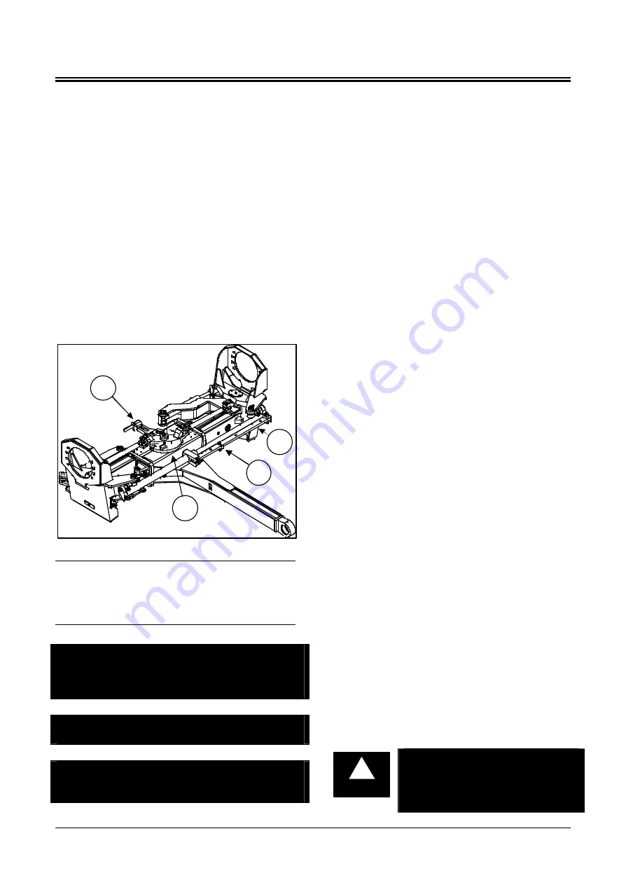
Adjustable (Front) Axle 

 
1. 

Locking pin 

2. 

Track Lock Disc 

3. 

Adjustment bar 

4. 

Pin 


NOTE: In order to be able to set the track width, 
the traction control lever must be moved out of 
neutral, field mode must be selected and the lock 
switch must be on.  


NOTE: Track width 1.50 m is only available on 
tires 300/95 R46. 


NOTE: Track lock disc and adjustment bar need 
to be changed when other tires or rims are 
mounted. 

Sliding the Axle 

If the track lock disc and the adjustment bar are 
fixed in either position one, two or three the axle 
can be sledded as following: 

1.  Depress the switch for the track width lock, and 

put the field / road switch in the field position. 

2.  To change the track width of the rear axle, move 

the traction control lever slightly forward so that 
the machine drives forward slowly. Then press 
the switch for changing the rear axle track 
width. Hold the button depressed until the bar 
on the track lock disc is pressed against the 
stop and the pin in the adjustment bar is 
pressed against the stop. 

3.  To change the front axle track width, move the 

traction control lever back so that the machine 
reverses slowly. Then press the switch for 
changing the front axle track width. Hold the 
button depressed until the bar on the track lock 
disc is pressed against the stop and the pin in 
the adjustment bar is pressed against the stop. 

4.  Unlock the switch for track width lock. 

Setting the Track Width 

The axle can slide between two different tracks de-
fined by the position of the track lock disc and the 
pins in the adjustment bar. Other tracks can be 
chosen by putting the track lock discs and the pins 
in the adjustment bar in another position. The tracks 
can be set as following: 

1.  Slide the axle a little bit in or out so that there is 

no tension on the locking pin in the track lock 
disc and the pins in the adjustment bar. 

2.  Pull the locking pin back. The track lock disc 

can be turned now. Put the locking pin in the 
bore hole corresponding to the track widths you 
need. See pictures on page 5.6 and 5.7. Slide 
the axle a bit in or out when the stops on the 
track lock disc hit the bar and prevent the disc 
from turning. 

3.  Take out the pins in the adjustment bar. Put the 

pins on the right place into the adjustment bar 
corresponding to pictures on page 5.6 and 5.7. 
All the pins are marked. Every track width has 
its own pin. The pins are marked with either “F”, 
Front axle or “R”, Rear axle and the track width. 
On track width 2.25 m no pin is used. Don’t 
swap pins. This will result in a wrong toe-in ad-
justment. 


WARNING

!


Caution: Don’t swap pins on the 
adjustment bar. This can result in 
a wrong toe-in adjustment. On 
track width 2.25 m no pin is used. 

Summary of Contents for ROGATOR 418

Page 1: ...Model Year 2005 ROGATOR 418 CATERPILLAR 3056E ENGINE HYDROSTATIC DRIVE OPERATOR S MANUAL P N 611871 A...

Page 2: ...eside the symbols DANGER An extreme inherent hazard ex ists which could result in injury or death if proper precautions are not taken WARNING A hazard exists which could re sult in injury or death if...

Page 3: ...Never operate the vehicle s engine inside a building unless adequate ventilation is pro vided to safely and properly remove the exhaust fumes NEVER modify or tamper with the exhaust system in any way...

Page 4: ...raulic System 02 4 Engine Coolant Level 02 4 Wheel Mounting Bolts 02 4 Maintenance Schedule 02 4 Chassis and Cab Modifications 02 4 Towing 02 4 Towing wi th Engine Operable 02 4 Towing with Engine Dis...

Page 5: ...rameters 04 6 The alarm display screen 04 7 Pop up messages and warnings 04 7 Configuration 04 8 OPERATION 05 Before Starting the Vehicle Engine 05 1 Starting the Engine 05 2 Restarting a Stalled Engi...

Page 6: ...and Decals 06 17 Safety Treads 06 17 Maintenance Parts RG618 06 17 COLD WEATHER OPERATION 07 Minimising the effect of cold weather 07 1 Seasonal viscosity Oil and Proper coolant concentration 07 1 Id...

Page 7: ...hicle and how to use all con trols properly BEFORE OPERATION Do not let anyone operate the vehicle systems or perform service and maintenance procedures without the proper instruction Keep the vehicle...

Page 8: ...vehicle system Do not turn the key switch to the OFF position until the vehicle is stopped and the vehicle is shut down properly Never carry more than the recommended load capacity of the vehicle Nev...

Page 9: ...Avoid sharp turns on hills When driving parallel on steep slopes beware that the vehicle doesn t roll over Never drive near the edge of a gully or steep embankment Travelling on Public Roads ALWAYS w...

Page 10: ...objects are ever in the path of the booms before operating them especially when folding or unfolding them Be aware of the location of the booms at all times Before driving on public roads fold and lo...

Page 11: ...of exposure to high decibels or loud noise Safe Handling of Fuel Avoid Fires Handle fuel with care it is highly flammable Always stop the engine before refuelling the vehicle Never refuel the vehicle...

Page 12: ...fety guards and shields Wear close fitting clothing Stop the engine and make sure the power takeoffs are stopped before making any adjustments or performing any type of service on the en gine or vehic...

Page 13: ...ere hazardous chemicals will not drift or run off to contaminate people animals vegetation water supply etc If hazardous chemicals come in contact with the body wash immediately according to the chemi...

Page 14: ...lectrical shorts or other personal injury when in contact with machine tools or moving parts Stop the engine remove the key and allow the vehicle to cool Keep all parts in good condition and properly...

Page 15: ...and procedures can create safety hazards Use only the proper equipment and procedures Use power tools only to loosen threaded parts and fasteners not to tighten the treaded parts Use only imperial to...

Page 16: ...ry or skin irritation If an accident does occur get medical help immediately if any personnel are injured by hydraulic fluid or fuel Any fluid injected into the skin must be surgically removed within...

Page 17: ...ed remove the stripper with soap and water before welding Remove solvent or paint stripper containers and other flammable material from the area Allow fumes to disperse before welding or heating Batte...

Page 18: ...ere can damage the earth s atmosphere Government regulations require a certified air conditioning service centre to recover and recycle used air conditioning refrigerants Mobile Radio Installations Un...

Page 19: ...only Diesel specified to EN590 E552394 2 Don t open hood with engine running E720561 8 Decal 418 E558992 3 Caution Read operator s manual E720568 9 Warning Stay outside the rotation area of the steps...

Page 20: ...6 Oil E558586 14 Warning Do not put limbs between the wheels and frame when the engine runs Tires and wheels can move without warning and crush you You can be killed or seriously injured E558580 17 Ca...

Page 21: ...If you want to fold in or out the steps be aware that there are no persons inside the rotation area of the steps E558571 21 If the machine is tipping over do not try to jump off but hold firmly on th...

Page 22: ...tion about the safe operation and maintenance of the RoGator More information is given in the Parts Manual s These are also supplied by manufacturers of Ag Chem Europe BV com ponents If there is anyth...

Page 23: ...BV identification plate with the serial number is located on the front panel of the compartment in the cabin AG CHEM SERIAL NUMBER Identification plate with serial number Engine Serial Number The engi...

Page 24: ...otors The RoGator has two possible travel mode switch positions 1 Field position 2 Road position When driving with the travel mode switch in the field position the vehicle speed is not controlled with...

Page 25: ...Check all items shown under the daily section of the maintenance schedule every day the machine is in use Chassis and Cabin Modifications IMPORTANT It is not allowed to modify the vehicle or auxiliary...

Page 26: ...disengagement 5 Open the lock valve at the centre of the chassis 6 The vehicle can be towed Lock Valves The lock valves are closed Position when driving Transport IMPORTANT If transporting the vehicle...

Page 27: ...ng 7 Electrical system earth switch 8 Batteries 9 Hydraulic tank 10 Hydraulic tank suction return line filter 11 Hydraulic tank filler opening 12 Fuel tank 13 Fuel tank filler opening 14 Wheel motor 1...

Page 28: ...the steer ing wheel in the direction you want Pull the steering wheel out to the desired position Tighten the handel on the left side of the steering column to lock the steering wheel in the desired p...

Page 29: ...e Field Position The machine is being driven with the throttle Move the lever slowly back from the neutral position to increase the reversing speed Move the lever slowly forward to reduce the reversin...

Page 30: ...t under the trac tion control lever Then turn the traction control lever to the desired position Subsequently tighten the clamping nut and the knurled nut 2 Adjusting the traction control lever consol...

Page 31: ...le switch is disabled PLEASE NOTE The ignition must be running in order to be able to release the parking brake PLEASE NOTE When the parking brake is en gaged the ladder will be lowered When the parki...

Page 32: ...t used 8 Spraypump On Off switch 9 Dubbel foam switch 10 Differential Lock On Off switch Optional 11 Folding Unfolding Booms switch 12 Second Fold switch 13 Half Fold switch 14 Purge switch 15 Regulat...

Page 33: ...ually Driving in the Field or on the Road For driving on public roads the field road switch is set to the road position and for working in the field to the field position When this switch is in the ro...

Page 34: ...or reduced with this switch if the switch mentioned above is in the on position Spraypump on off Only in combination with spraypack Res 1 Res 2 Option switches only in combination with spray pack Con...

Page 35: ...he outside of the door and turn the key clockwise to lock the door and anti clockwise to unlock the door Subsequently return the key to the original position and remove the key Doorlatch Sun Visor Pul...

Page 36: ...xtension upwards over the various incre ments to adjust the backrest extension for height 8 Lumbar support Turn the adjustment knob to the left or right to ad just both the height and curvature of the...

Page 37: ...ss the bottom of the switch to turn the light off 5 Beacon Light Switch Option Press the top of the switch to turn the light on Press the bottom of the switch to turn the light off 6 Hazard Warning Sw...

Page 38: ...o wheel steer mode 9 Front axle in middle position 10 Speedometer 11 Battery Voltage gauge 12 Fuel level gauge 13 Left turn signal indicator 14 High beams on 15 Parkingbrake on 16 Right turn signal in...

Page 39: ...er or the leak oil filter is becoming restricted The filters must be changed Boost Pressure Indicator Light This indicator light illuminates when the boost pres sure drops below 16 bar Hydraulic Oil L...

Page 40: ...data Graphs Multi data a combination of the above Current active alarm messages Additionally various diagnostic screens are acces sible allowing detailed investigation of the en gine s data stream Ge...

Page 41: ...ls that allow the display to be read in the dark The appropriate level is selected by pressing key 1 to decrease the illumination or key 2 to increase it Adjusting the contrast of the LCD to an optimu...

Page 42: ...displayed sequentially in re sponse to repeated presses of key 2 Using the adjust mode each individual gauge displayed on the screens can be configured by the user to show a different engine paramete...

Page 43: ...enu from 2 10 or 30 minutes up to 1 2 4 or 8 hours The maximum and minimum values of the Y axis defining the span of readings displayed are ad justed automatically to give the optimum view of the visi...

Page 44: ...d 2 The screen cannot be exited until all alarms have been acknowledged by pressing key 3 Alarm messages will be automatically cleared from the list if no longer received The alarm list screen can be...

Page 45: ...mes sages and prompts Use the up and down keys key 1 and key 2 to high light the required language and then press key 4 to select it Pressing key 5 returns the user to the main SETTINGS menu BLEEP se...

Page 46: ...ich is stored in Flash memory onto the CAN bus Any other GEM displays on the bus will be updated with the application program from the transmitting GEM Press the OK key to initiate programming Note It...

Page 47: ...e oil must be visible in the sight glass Add oil if necessary but do not over fill Check all the items under Every 10 hours or daily in the Service Manual Adjust the seat so that all instruments and c...

Page 48: ...TELY in order to prevent a marked rise in temperature Continue working or allow the engine to run at 1000 1200 rpm for two minutes before stopping the en gine Starting at Low Temperatures See the engi...

Page 49: ...s moved in a certain direction 5 Select the correct gear for the desired accelera tion and also the desired engine speed 6 To stop the vehicle move the traction control lever to neutral from forward o...

Page 50: ...ing in the tramlines with the 4 wheel steering switched on can cause an unstable drive of the ma chine and excessive boom motion Manual This is the calibration position for the all wheel steering If...

Page 51: ...lly as soon as the manual mode switch is toggled up or down Bet ter access to the machine can be gained by using the manual mode switch toggled down to drop the suspension to its minimum value WARNING...

Page 52: ...track lock disc is pressed against the stop and the pin in the adjustment bar is pressed against the stop 3 To change the front axle track width move the traction control lever back so that the machin...

Page 53: ...OPERATION 05 7 Operation 11 04 RoGator 418 F 1 50 F 2 00 Position Track lock disc Track width 1 50 m 2 00 m Front axle Track width 1 80 m 2 25 m Front axle F 1 80 No Pin Position Track lock disc...

Page 54: ...g axle The axle needs to be slided once a week in the sea son to prevent the axle tubes from getting stuck Clean the slide axle once a week or every 50 hours and lubricate the sliding surfaces with gr...

Page 55: ...switch activates or deactivates the engine speed governor The switch inside the cab must be turned off Engine Speed Switch The engine speed can be raised or reduced with this switch if the switch men...

Page 56: ...vels after filling by using the indicators IDENTIFICATION RECOMMENDED CAPACITY HYDRAULIC SYSTEM ISO VG 46 200 L ENGINE COOLANT Caterpillar diesel engine antifreeze coolant Or commer cial heavy duty co...

Page 57: ...rating hours Grease lubrication every 50 hours Oil lubrication every 50 hours Service interval reminder Pressurized Drain empty Engine oil Engine oil level Engine oil filter Engine coolant level Hydra...

Page 58: ...Check the hydraulic pipes hoses X X 11 Check the compressed air hoses X X 12 Check the V belts X X 13 Clean the combined cooler X X 14 Lubricate the steering ball joints X X 15 Clean and lubricate th...

Page 59: ...MAINTENANCE 06 4 Maintenance 11 04 RoGator 418 ROGATOR 418 418 ROGATOR 418 ROGATOR 418 0 0 1 1 1 3 4 5 6 7 8 8 9 12 13 17 18 18 20 21 21 22 23 24 25...

Page 60: ...MPORTANT Do not add any oil until the oil level is below the ADD mark 1 Stop the engine 2 Do not operate the engine for at least 10 min utes in order to allow the engine oil to return to the oil pan 3...

Page 61: ...level between the ADD and FULL marks on the oil level gauge Engine Oil Filters Engine Oil Filters Engine Belts Check the tension of the V belts every 50 hours of operation Adjust the belt tension if...

Page 62: ...t Direct the air through the element in the oppo site direction of normal flow through the ele ment 2 Move the nozzle up and down while turning the element Keep the nozzle a minimum of one inch from t...

Page 63: ...el can cause gumming to form Gumming will cause fuel filters and other parts of the fuel system to clog Keep dirt water and for eign material out of the fuel Do not keep any fuel for a long period of...

Page 64: ...iming pump 3 until the fuel flows out of nut 2 free of air Priming lever 3 Priming pump 4 Priming lever 3 Tighten nut 2 to a torque of 23 Nm 4 If the fuel line for the air inlet heater has been draine...

Page 65: ...in structions when installing a tyre on a wheel or rim can produce an explosion that can cause personal injury or death DO NOT attempt to install a tyre unless you have the correct equipment and are...

Page 66: ...e 1 1 4 turn 2 Tighten to a torque of 250 Nm 3 Tighten each wheel mounting bolt accord ing to wheel bolt tightening sequence pic ture 4 Tighten to a torque of500 Nm 5 Retighten every 500 hours of oper...

Page 67: ...or cleaned regularly The RoGator must be washed regularly to remove any dangerous material adhering to the RoGator The washing water cleaning cloths and vacuum cleaner waste which may contain dangero...

Page 68: ...ht comes on Replacing the Suction and Return Line Filter 1 Put the vehicle on level ground 2 Clean the filter element cover and the sur rounding area 3 Loosen the four M10 nuts at the filter cover the...

Page 69: ...ttery DANGER Disconnect the battery terminals before beginning to service the electrical system DANGER NEVER charge a frozen battery It could explode and cause se vere personal injury Let the battery...

Page 70: ...Hazard lights F20 10A Dash and courtesy lamps F21 1A not used F22 15A Acc run enable F23 15A Chair F24 25A Wiper and washer F25 10A Run acc startrelays F26 1A turn signal switch power F27 5A Horn F28...

Page 71: ...e or frame Then remove the cable from the Ro Gator battery positive terminal Storage of Vehicle If the vehicle is in storage for several months the following procedures will help prevent excessive det...

Page 72: ...d Decals Wash the vehicle with water and a de tergent Automotive cleaners and waxes can also be used Paint areas that are damaged Replace any decals or safety signs that are damaged or missing immedia...

Page 73: ...on level Coolant solutions of quality water ethylene glycol concentrate antifreeze and supplemental coolant additives SCA s MUST be used year round for freeze protection boil over protection liner ero...

Page 74: ...ual of the engine Mixing of Lubricants In General avoid mixing different brands or types of oil Oil manufacturers blend additives in their oils to meet certain specifications and performance re quirem...

Page 75: ...TANT Do NOT store diesel fuel in ga l vanized containers Diesel fuel stored in galva nized containers reacts with the zinc coating on the container to form zinc flakes If fuel con tains water a zinc g...

Page 76: ...in a cool dry place and keep them fully charged 10 Clean the exterior of the engine with salt free water and touch up any scratched or chipped painted surfaces with good quality paint 11 Coat all exp...

Page 77: ...re Clean or replace the air filter Starter speed low and the engine cranks slowly Connections loose or cor roded Battery earth switch faulty Low battery voltage Incorrect viscosity of the engine oil S...

Page 78: ...Europe b v service centre Clean the charge air cooling system contact Ag Chem Europe b v service centre Electrical System PROBLEM POSSIBLE CAUSE CORRECTION The voltage in the electrical sys tem is low...

Page 79: ...tem Replace the hydraulic oil filter Contact Ag Chem Europe b v service centre Hydraulic system oil overheats Oil level to high low Oil cooling system radia tor restricted Blower not running Blocked o...

Page 80: ...Cab windows fog up Excessive moisture in cab air system Position the air vents toward the windows Use the air conditioner system and re circulation control along with the heating system to dehumidify...

Page 81: ...indicators four way flashers tail brakes lights instrumental panel lights cab entry lighting triple utility outlets for cell phones radios etc Fuse panel for lighting elec tronics engine and other ele...

Page 82: ...shields wheel motor Central Lubrication System Tire Inflation System Traction control Speed ground radar Work Lights Radio CD Player Chassis weights Axle Weight Front axle weight 4700 kg Rear axle we...

Page 83: ...entative Maintenance 6 17 Cabin 9 4 Cabin light switch 3 8 Changing the Engine Oil and Oil Filter 6 5 Chassis and Cab Modifications 2 4 Chassis Specifications 10 1 Chassis Weights 10 2 Checking the Oi...

Page 84: ...EX INDEX Inner Filter Element 6 8 Installing the Wheels 6 11 Instrument Panel 3 5 INSTRUMENT PANEL 4 Instrument panel dashboard 4 1 INTRODUCTION 2 J Jump Starting 6 16 K L Left turn signal light 4 2 L...

Page 85: ...anges 10 1 Speed Ranges 5 3 Speedometer 4 2 Spray pump On Off 3 7 Spray pump On Off 5 9 Starting at Low Temperatures 5 2 Starting the Engine 5 2 Stay Clear of Rotating Power Takeoffs and Moving Parts...

Page 86: ...3 Using the soft keys 4 4 V W Warning cold start lamp 3 10 Water quality 7 1 Wear Protective Clothing 1 8 Weight adjustment 3 9 Wheel Maintenance 6 11 Wheel Motors 10 1 Wheel Mounting Bolts 2 4 Windsh...

Reviews: