


Mounting
and
commissioning
6.2
Mounting the wall holder
Use the enclosed screw (4 x 30 mm) and, if necessary, a dowel
(6 mm) to mount the wall holder for the DIT 01 tank contents in-
dicator at the desired location.
6.3
Mounting the junction box
The provided moisture-proof junction box is not suitable for exterior
application.
1.
For exterior application use the exterior junction box, refer to
chapter 11, page 23.
2.
Use the enclosed screws and, if necessary, dowels, to mount
the junction box for connecting the pressure sensor cable and
the cable of the digital unit at the desired location. Make sure to
provide sufficient cable length. The digital unit must be able to
be removed from the wall holder, e.g. if you need to replace the
battery.
2.
Place the digital unit into the wall holder and route the cable into
the junction box.
3. Push
the
connection
elements
required for the tank connection
(PG connection, screw connection or Euroflex) onto the pres-
sure sensor cable in the correct sequence and orientation.
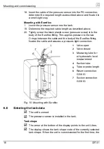
6.4
Cable connection
1.
Route the cable of the pressure sensor to the junction box and
connect the two cables by means of the insulating screw joint.
Make sure to connect the wires of the same colour, respectively.
Digital unit
1
White (U+)
2
Green (signal)
3
Brown (U-)
4
Yellow/black (screen)
5
Insulating screw joints
6
Pressure sensor
7
Fig. 3: Cable connection
DIT 01
13