


P a g e
|
30
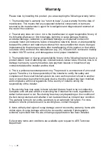
Relay Wiring Examples
Additional Wiring Tips
Relay
STRIKE
LOCK
Relay
MAGNETIC LOCK
DISCLAIMER
:
These diagrams are for
demonstrational use only. Please use the
manufacturer’s instructions provided with the lock.
Note:
The
manufacturer is
not responsible
for wiring to
third party
devices. Please
consult the
device
instructions if
having issues.
8GB
SD
C
AR
D
U
SB
Re
la
y
2
Re
la
y
1
FCO N
S CA
1 50 0
6 .3 V
FCO N
S CA
1 50 0
6 .3 V
FCO N
S CA
1 50 0
6 .3 V
220
50V
R
VT
FCO N
S CA
1 50 0
6 .3 V
FCO N
S CA
1 50 0
6 .3 V
101
2
20
Q
U
E
C
TE
L
Q
U
E
C
TE
L
Q
U
E
C
TE
L
Q
U
E
C
TE
L
Relay1
Relay 2
COM
N/O
N/C
COM
N/O
PRESS
TO EXIT
Optional
Exit Button
Separate
lock PSU
Driveway
Gates
Gate
Controller
N/C
N/C
Magnetic Lock
Summary of Contents for KEY-AUX-PBPK-US
Page 3: ...P a g e 3 PHASE 1 Site Survey...
Page 5: ...P a g e 5 PHASE 2 Product Overview...
Page 7: ...P a g e 7 Overview of Intercoms Flush Design Antenna Separate...
Page 16: ...P a g e 16 PHASE 3 Setup Programming To be done before installing the intercom...
Page 27: ...P a g e 27 PHASE 5 Installation...
Page 33: ...P a g e 33 PHASE 6 Aftercare...
Page 42: ...P a g e 42...
Page 43: ...P a g e 43...