background image

23

C.  C2 will be displayed. With the control in this position, 

check to see that the water is being drawn out of the 
regenerant tank. The water level in the regenerant 
tank should recede very slowly.

D.  Observe that water is being drawn from the 

regenerant tank for at least three minutes. If the 
water level does not recede, check all regenerant line 
connections for air leaks.

8.  If the water level is receding from the regenerant tank, you 

can quick cycle the control back to the treated water position 
by pressing SET and the UP buttons simultaneously.

9.  Finally, turn on a faucet plumbed after the water conditioner. 

Run the faucet until the water runs clear.

10.  Add the appropriate amount of regenerant to the regenerant 

tank. 

The Water Conditioning System  

is Now Fully Operational.

Placing WC400 Water Conditioning System 
Into Operation (Fill Brine Tank First)

Quick Cycling the Analyzer Control

It is required that the control be quick cycled to specific 
regeneration cycles when placing the conditioner into operation. 
Please review the following instructions for quick cycling the 
control before proceeding to startup.
1.  With the control in the treated water position, press and 

hold the REGEN button on the control for five seconds. This 
will initiate a manual regeneration. The control will display 
an hourglass indicating that the motor and camshaft are 
turning. The control also displays the total regeneration time 
remaining. When the control reaches the pre-pressurize cycle, 
the hourglass is no longer displayed and the motor will turn 
off. Pressing the SET button will display the time remaining 
for the current cycle.

2.  Press and release the UP and SET buttons to move the control 

to the next cycle. 

Note: 

The control can be sent directly back to the treated 

water position from any regeneration cycle. Press and hold the 
UP and SET buttons (about five seconds) until the hourglass 
icon appears solid. The control will now skip all remaining 
regeneration cycles.

Startup

After you have performed the previous initial power-up steps, 
you will need to place the conditioner into operation. Follow 
these steps carefully, as they differ from previous WC400 valve 
instructions.
1.  Remove the cover from the valve. Removing the cover will 

allow you to see that the camshaft is turning, and in which 
cycle the camshaft is currently positioned.

2.  With the supply water for the system still turned off, position 

the bypass valve to the “not in bypass” (normal operation) 
position.

3.  Press and hold the REGEN button on the Analyzer control for 

five seconds. This will initiate a manual regeneration. The 
control will display an hourglass indicating that the motor 
and camshaft are turning. The control also displays the total 
regeneration time remaining. When the control reaches the 
repressurize cycle (C4), the hourglass is no longer displayed 
and the motor will turn off. Pressing the SET button will 
display the time remaining for the current cycle.

4.  Press and release SET and UP simultaneously to advance  

to each cycle.

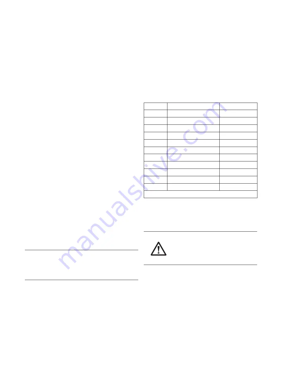
5.  Advance the control to the Backwash cycle (C1).  

See Cycle Sequence Table. 

Cycle Sequence Table

C# 

 Cycle Description

Time in Minutes

C0

Service

C4*

Repressurize

3

C8

Brine Refill 

Calculated

C0

Brine Make-up

120

C1

Backwash

14

C2

Brine Draw

Calculated

C3

Slow Rinse

Calculated

C4*

2nd Repressurize

3

C5

Fast Rinse

6

C6

2nd Backwash

1

C7

2nd Fast Rinse

1

*Note: C4 repressurization does not have flow to drain.

6.  Fill the media tank with water.

A.  While the controller is in the backwash (C1)  

cycle, open the water supply valve very slowly  
to approximately the 1/4 open position.


WARNING: 

If opened too rapidly or too far, 

media may be lost out of the tank into the valve 
or the plumbing. In the 1/4 open position, you 
should hear air slowly escaping from the valve 
drain line.

B.  When all of the air has been purged from the media 

tank (water begins to flow steadily from the drain 
line), open the main supply valve all of the way. This 
will purge the remaining air from the tank.

C.  Allow water to run to drain until the water runs clear 

from the drain line. This purges any refuse from the 
media bed.

D.  Turn off the water supply and let the system stand for 

about five minutes. This will allow any air trapped to 
escape from the tank.

7.  Add water to the regenerant tank (conditioner only).

A.  With a bucket or hose, add enough water to the 

regenerant tank to have water visible.

Summary of Contents for Origins WC400

Page 1: ...Operation Manual 00947 1864 EA 03632...

Page 2: ...ays Icons and Cursors 16 Button Functions 16 Programming Overview 17 Control Operation 17 Level I Programming 17 Level l Programming 18 Level II Programming P Values 19 Programming the Lockout Feature...

Page 3: ...ofteners shall have a rated salt efficiency of not less than 3350 grains of total hardness exchanged per pound of salt based on NaCI equivalency 477 grams of total hardness exchanged per kilogram of s...

Page 4: ...tions should be hand tightened Plumber tape may be used on connections that do not use an O ring seal Do not use pipe dope type sealants on the valve body Do not use pliers or pipe wrenches Do not use...

Page 5: ...04 m3 Recharge Salt Tank Size 19 x 36 48 3 x 91 5 cm Salt Storage 240 lbs 109 kg Drain Water Rate 3 9 gpm 14 7 L m Service Connection Size 1 NPT Drain Connection Size 3 4 NPT Recharge Brine Connection...

Page 6: ...itioning system outdoors several items must be considered Moisture The valve and control are rated for NEMA 3 locations Falling water should not affect performance The system is not designed to withst...

Page 7: ...lar 4 Base 12 Riser Tube 5 268 Logix PE Valve w 716 Control 13 Upper Basket 6 Resin Tank 14 Cover 7 Door Access Sensor 15 Shield 8 Sensors Wired Probes Brine Tank 1 Cover 5 Brine Tube Assembly 2 Colla...

Page 8: ...8 Equipment Installation Dimensions 36 9 938 1 60 7 1541 6 19 8 503 8 16 8 427 1 17 6 447 20 5 521 1 35 1 890 4 28 2 715 9 32 2 817 5 53 4 1356 6 55 1398 1 5 0 127 2 5 63 5...

Page 9: ...Floor Drain Figure 1 Standard Basement Before Installation Cold water lines shown Soft Water Hard Water Outside Faucet Outside Faucet Bath Tub Lavatory Toilet Kitchen Laundry Tubs Pump or Meter Hot W...

Page 10: ...e for now To Assemble the Media Tank 1 If the floor under the media tank is uneven the leveling feet may be installed Slowly lay the tank on its side Press or tap the feet into the pockets WARNING The...

Page 11: ...S S B Y P A S S B Y P A S S Water Conditioner Water Conditioner In Out In Out Figure 7 Model 1265 Bypass Included Water Conditioner Water Conditioner Water Conditioner Water Conditioner Normal Operati...

Page 12: ...drain line connection This will provide an adequate siphon trap Tie or wire the hose in place at the drain point Also provide an air gap of at least 1 1 2 inch between the end of the hose and the drai...

Page 13: ...ing Secure hose in place Drain Air Gap Figure 12 Electrical Connection Note There are no user serviceable parts in the AC adapter motor or the control board The Analyzer control operates on a 12 volt...

Page 14: ...ses Slow Rinse Downflow Cycle C3 Water flow moves the regenerant through the resin at a specific rate and rinses to the drain The resin is regenerated Repressurization Cycle C4 Pressure is balanced in...

Page 15: ...ic disinfection during their normal life Depending upon the conditions of use the style of conditioner the type of ion exchanger and the disinfectant available a choice can be made among the following...

Page 16: ...he control is moving to a regeneration cycle Appears as a solid icon during a cancelled regeneration and the control is cycling directly back to the home position 13 Indicates the selected program set...

Page 17: ...tion in memory for 8 to 24 hours depending on the installation If the super capacitor is exhausted the Analyzer control will display four dashes immediately upon power up The Time of Day and Day of We...

Page 18: ...3 Time Day Regeneration Time Day Time Day Regeneration Time Day Time Day Regeneration Time Day Time Day Regeneration Time Day Time Day Regeneration Time Day Time Day Regeneration Time Day Time Day Reg...

Page 19: ...lt Setting 3 18 50 290 1 10 9 110 Lbs Cu ft3 g L Set in Level I Programming P7 Capacity View Only 1 140 0 1 14 0 1 0 1 Calculated Kilograins Kilograms Values dependent on P9 setting P8 Not Used P9 Uni...

Page 20: ...Flow rate dictated by size of drain line flow controller C2 Regenerant Draw Not Adjustable 1 Min See Notes Automatically calculated from resin volume and salt dosage settings C3 Slow Rinse 0 200 1 Min...

Page 21: ...5536 H9 Months since unit last serviced 0 255 Holding the set key down for three seconds while H4 number of regenerations since last reset is being displayed will reset the numbers stored in H4 H5 H6...

Page 22: ...mately the 1 4 open position Water will begin to enter the media tank Air will begin to be purged to drain as the media tank fills with water WARNING If the supply valve is opened too rapidly or too f...

Page 23: ...operation Follow these steps carefully as they differ from previous WC400 valve instructions 1 Remove the cover from the valve Removing the cover will allow you to see that the camshaft is turning and...

Page 24: ...d recede very slowly B If the water in the regenerant tank does not recede or goes up refer to the Troubleshooting section 11 If the water level is receding from the regenerant tank wait for the tank...

Page 25: ...235352 Cam Valve Black 1 18 1010154 O Ring Tank 1 7 4002917 Cover Medium Gray 1 19 1232370 O Ring Riser Tube 1 4002918 Skirt Medium Gray 1 20 61893 Probe Cable Clips Kit 1 8 3019151 Transformer 120 VA...

Page 26: ...nt 12 Tank 1 22 4000359 Spring Torsion 2 7 4000352 Collar Jacket Resin Tank 1 23 4002932 Latch Cover Medium Gray 2 8 4000987 Lower Distributor Assy 12 x 48 Tank 1 24 1396149 Washer Stainless Steel 4 9...

Page 27: ...m Part Number Description Qty 1 CH15013 1 Brine Well w Slots 1 2 60014 Safety Brine Valve 1 3 CH15070 Grommet 2 4 CH16371 60 Tubing 3 8 x 60 Long 1 5 CH15024 Cap Brine Well 4 Dia Caplug STP 4 2 6 6006...

Page 28: ...harness motor optical sensor assembly 2 Control Camshaft is turning more than five minutes to find Home position Verify that optical sensor is in place and connected to wire Verify that camshaft is c...

Page 29: ...ing to instructions b Remove restriction c Clean injector and screen d Replace injector and cap Contact dealer e Remove foreign matter from disc and check disc for closing by pushing in on stem Replac...

Page 30: ...lines or failure of the plumbing hook up Ordinary wear and tear shall not be considered a defect in workmanship or material Servicing your WC400 by parties other than an authorized Aerus representativ...

Page 31: ...Manuel d utilisation ADOUCISSEUR D EAU WC400 00947 1864 EA 03632...

Page 32: ...ges ic nes et curseurs 47 Fonctions des touches 47 Vue d ensemble de la programmation 48 Fonctionnement du contr leur 48 Programmation de niveau I 48 Programmation de niveau I 49 Programmation de nive...

Page 33: ...grammes de duret totale chang s par kilogramme de sel selon un quivalent NaCL 3 350 grains de duret totale chang s par livre de sel et ne pas diffuser plus de sel que ce qui est indiqu dans ses param...

Page 34: ...filet s peut tre utilis sur les raccords sans joint torique N utilisez pas de type de scellant comme de la p te joint sur le corps de la vanne N utilisez pas des pinces ou des cl s tuyau N utilisez p...

Page 35: ...Capacit de stockage de sel 109 kg 240 lb D bit d eau d vacuation 14 7 L m 3 9 gpm Dimension du raccord pour le service 1 po NPT Dimension du raccord pour la vidange 3 4 po NPT Dimension du raccord po...

Page 36: ...appropri es de levage pour d placer l appareil Emplacement l ext rieur Il est recommand que l adoucisseur WC400 soit install dans un environnement prot g Lorsque le syst me d adoucissement d eau doit...

Page 37: ...r 4 Socle 12 Colonne montante 5 Vanne 268 Logix PE avec contr leur 716 13 Panier sup rieur 6 R servoir de r sine 14 Couvercle 7 Porte acc s sonde 15 Protecteur 8 Sondes c bl es Bac saumure 1 Couvercle...

Page 38: ...38 Installation de l quipement Dimensions 36 9 938 1 60 7 1541 6 19 8 503 8 16 8 427 1 17 6 447 20 5 521 1 35 1 890 4 28 2 715 9 32 2 817 5 53 4 1356 6 55 1398 1 5 0 127 2 5 63 5...

Page 39: ...us sol normal avant l installation Tuyauterie d eau froide illustr e Eau douce Eau calcaire Robinet d ext rieur Robinet d ext rieur Bain Lavabo Toilette Cuisine Cuve de lessivage Pompe ou compteur Sor...

Page 40: ...Installez le raccord de trop plein 6 Placez le collier du r servoir par dessus le cylindre de saumure Mettez en place le collier et pressez vers le bas sur le r servoir Mettez le couvercle de c t pou...

Page 41: ...deux poign es sur la vanne de d rivation 2 ou 3 fois Ceci aidera bien fixer les joints toriques et pr venir une fuite Fonctionnement normal En d rivation B Y P A S S B Y P A S S B Y P A S S B Y P A S...

Page 42: ...hez l extr mit du tuyau en place proximit du siphon Assurez un espace de 3 8 cm 1 1 2 po entre l extr mit du tuyau souple et le siphon de sol 5 Lorsque le tuyau de vidange se vide dans une conduite d...

Page 43: ...plein Tuyau souple de vidange Fixer le tuyau en place Siphon de sol Espace Figure 28 Connexion lectrique Note Il n existe aucune pi ce r parable dans l adaptateur CA le moteur ou le contr leur Le con...

Page 44: ...t Cycle C3 Le flux d eau d place la solution r g n ratrice travers la r sine un taux pr cis et les impuret s sont rinc es vers l gout La r sine est r g n r e Cycle de l eau Lavage contre courant Rin a...

Page 45: ...au cours de leur dur e de vie normale Selon les conditions d utilisation le style d adoucisseur le type d changeur d ions et le d sinfectant disponible un choix peut tre fait parmi les m thodes suiva...

Page 46: ...de r g n ration S affiche comme une ic ne lumi re continue lors d une r g n ration annul e et le contr leur retourne la position initiale du cycle 13 Indique que le param tre du programme s lectionn e...

Page 47: ...n dans la m moire pendant une dur e de 8 24 heures selon le type d installation Si le supercondensateur est puis quatre tirets s afficheront sur le panneau du contr leur imm diatement au d marrage Les...

Page 48: ...e estim e affichage seulement bas e sur le volume de r sine et le param tre de sel 1 Type de vanne S lectionner le mod le Quantit de sel DIM LUN MAR MER JEU VEN SAM JOURS Capacit PM Heure Jour Heure J...

Page 49: ...l 3 18 50 290 1 10 9 110 lb pi3 g l R gler au niveau I de la programmation P7 Capacit affichage uniquement 1 140 0 1 14 0 1 0 1 Calcul Kilograins Kilogrammes Les valeurs d pendent du param tre P10 P8...

Page 50: ...du r gulateur de d bit et de la taille du tuyau de vidange C2 Pr l vement de la solution r g n ratrice Non r glable 1 min Voir les notes Calcul automatiquement d apr s les param tres de volume de r si...

Page 51: ...depuis le dernier entretien de l appareil 0 255 En maintenant enfonc e la touche R GLAGE pendant trois secondes tandis que H4 nombre de r g n rations depuis la derni re r initialisation est affich e...

Page 52: ...r s lentement environ 1 4 de la position ouverte L eau commencera entrer dans le r servoir de mati re filtrante L air sera purg vers le siphon alors que le r servoir de mati re filtrante se remplit av...

Page 53: ...s teint Lorsque vous appuyez sur la touche R GLAGE la dur e restante du cycle actuel s affichera 2 Appuyez puis rel chez les touches HAUT et R GLAGE pour faire avancer le contr leur vers la prochaine...

Page 54: ...GLAGE et HAUT simultan ment puis rel chez les pour faire avancer le syst me au cycle de production de la saumure Une fois le cycle de production de saumure atteint appuyez sur les touches R GLAGE et...

Page 55: ...Ressort disque de vanne 1 17 1035622 Anneau du r servoir 1 6 1235352 Arbre cames noir 1 18 1010154 Joint torique du r servoir 1 7 4002917 Couvercle gris moyem 1 19 1232370 Joint torique de la colonne...

Page 56: ...22 4000359 Ressort de torsion 2 7 4000352 Collier de l enveloppe du r servoir de r sine 1 23 4002932 Loquet du couvercle gris moyem 2 8 4000987 Ensemble distributeur inf rieur r servoir 30 cm x 121 c...

Page 57: ...ure avec fentes 1 2 60014 Vanne de s ret de saumure 1 3 CH15070 Bague 2 4 CH16371 60 Tuyau souple de longueur 0 9 x 152 cm 1 5 CH15024 Capuchon puits de saumure diam tre de 10 cm Caplug STP 4 2 6 6006...

Page 58: ...r leur L arbre cames tourne plus de cinq minutes pour trouver la position initiale V rifiez que le capteur optique est en place et connect au fil V rifiez que l arbre cames est connect correctement V...

Page 59: ...ettoyez l injecteur et le filtre d Remplacez l injecteur et le capuchon Contactez le fournisseur e Retirez tout corps tranger du disque et v rifiez le fonctionnement de la fermeture du disque en pouss...

Page 60: ...tuyaux de vidange ou la d faillance au niveau des raccords de plomberie Une usure normale ne sera pas consid r e un d faut de fabrication ou de mat riel L entretien de votre adoucisseur WC400 par des...

Page 61: ...61...

Page 62: ...62...

Page 63: ...renseignements concernant l utilisation de cet appareil appelez sans frais au 1 800 243 9078 U 1 800 668 0763 Canada WC4_WC400_UM_00947 1864_EA 03632_ENG FR_0414 For more information regarding the use...

Page 64: ...64...

Reviews: