background image

Mechanical Specifications and Installation

ABL1500WB-B Hardware Manual

26

Chapter 2

www.aerotech.com

This page intentionally left blank.

Summary of Contents for ABL1500WB-B Series

Page 1: ...Revision 1 02 00 ABL1500WB B Hardware Manual ...

Page 2: ...rvice aerotech com 101 Zeta Drive Pittsburgh PA 15238 2811 www aerotech com United Kingdom Japan Phone 44 0 1256 855055 Fax 44 0 1256 855649 Email service aerotech co uk Phone 81 0 50 5830 6814 Fax 81 0 43 306 3773 Email service aerotechkk co jp Germany China Phone 49 0 911 967 9370 Fax 49 0 911 967 93720 Email service aerotechgmbh de Phone 86 21 5508 6731 Email service aerotech com France Taiwan ...

Page 3: ...he Stage to the Mounting Surface 19 2 4 Attaching the Payload to the Stage 22 Load Capability 22 Chapter 3 Electrical Specifications and Installation 27 3 1 Motor and Feedback Connectors 29 3 2 Motor and Feedback Wiring 33 3 3 Motor and Feedback Specifications 34 3 3 1 Limit Operation with E3 Encoder Option 36 3 4 Limits Marker and Machine Direction 37 3 5 Motor and Feedback Phasing 38 Chapter 4 M...

Page 4: ...ffsets Varying C O G Height Laterally Centered Payload 24 Figure 2 9 Yaw Offsets Payload C O G 25 mm Above Tabletop 25 Figure 2 10 Yaw Offsets Payload C O G 50 mm Above Tabletop 25 Figure 3 1 Connector Locations 28 Figure 3 2 Motor and Feedback Wiring 33 Figure 3 3 E3 Encoder Option Limit Wiring 36 Figure 3 4 Machine Direction 37 Figure 3 5 Hall Phasing 38 Figure 3 6 Analog Encoder Phasing Referen...

Page 5: ...ons 13 Table 1 4 Air Specifications 14 Table 3 1 Motor Connector Pinouts 30 Table 3 2 Feedback Connector Pinouts 31 Table 3 3 User I O Option Connector Pin Assignments 32 Table 3 4 Feedback Specifications 34 Table 3 5 Encoder Specifications 35 Table 3 6 BLMC 192 Motor Specifications 35 Table 3 7 E3 Encoder Option Limit Signals 36 Table 4 1 Recommended Cleaning Solvents 41 www aerotech com 5 ...

Page 6: ...Table of Contents ABL1500WB B Hardware Manual 6 www aerotech com This page intentionally left blank ...

Page 7: ...product 6 PINCH POINT Keep Hands Clear while the stage is in motion W A R N I N G To minimize the possibility of electrical shock bodily injury or death the following precautions must be followed 1 Moving parts can cause crushing or shearing injuries Access to all stage and motor parts must be restricted while connected to a power source 2 Cables can pose a tripping hazard Securely mount and posit...

Page 8: ...Safety ABL1500WB B Hardware Manual 8 www aerotech com This page intentionally left blank ...

Page 9: ...ther more declares that it is not allowed to put the equipment into service until the machinery into which it is to be incorporated or of which it is to be a component has been found and declared to be in con formity with the provisions of the Directive 2006 42 EC and with national implementing legislation i e as a whole including the equipment referred to in this Declaration This is to certify th...

Page 10: ...Declaration of Conformity ABL1500WB B Hardware Manual 10 www aerotech com This page intentionally left blank ...

Page 11: ...racy incremental linear encoder 1 Vpp amplified sine output Cable Management Required CMS1 Single axis cable management system CMS2 Cable management system for XY assembly CMS3 Cable management system for XIO 2 extra cables 1 extra air CMS4 Cable management system for XYZ assembly CMS5 Cable management system for XYIO 2 extra cables 1 extra air Metrology Required PL1 Metrology uncalibrated with pe...

Page 12: ...system performance Contact Aerotech for information regarding your specific application Protection Rating ABL1500WB B stages have limited protection against particles and dust This equates to an ingress protection rating of IP50 Use Indoor use only 1 2 Accuracy and Temperature Effects Due to the small clearances in the air bearing design extreme temperature environments could cause a decrease in p...

Page 13: ...N Load Capacity 2 Horizontal 60 0 kg Side 25 kg Operating Pressure 3 80 psi 5 psig Air Consumption 4 32 40 slpm 551 kPa Moving Mass No Load 13 7 kg Stage Mass 50 2 kg 56 8 kg 64 0 kg 70 8 kg Material Aluminum Mean Time Between Failure 30 000 Hours 1 Certified with each stage 2 Axis orientation for on axis loading is listed refer to Section 2 4 for offset loading behavior 3 To protect air bearing a...

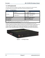
Page 14: ...m or 5 32 OD Hose 1 Recommended 2 The filtration requirement is to prevent particles from clogging the air bearing openings 3 Aerotech recommends using a polyurethane air hose Aerotech also recommends that you install a pressure switch P N MCA03094 tied to the motion controller s emergency stop ESTOP that will remove power to the air bearing if pressure drops below 40 psi a drop in pressure could ...

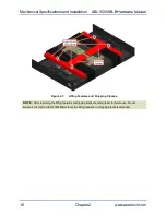
Page 15: ...ating the ABL1500WB B it is important to let it stabilize at room temperature for at least 12 hours Allowing it to stabilize to room temperature will ensure that all of the alignments preloads and tolerances are the same as they were when tested at Aerotech Use compressed nitrogen or clean dry oil less air to remove any dust or debris that has collected during shipping Lifting Hardware ABL1500WB B...

Page 16: ...al Figure 2 1 Lifting Features and Shipping Clamps N OTE After removing the lifting features or shipping brackets retain them for future use Do not transport or ship the ABL1500WB B without the lifting features or shipping brackets attached 16 Chapter 2 www aerotech com ...

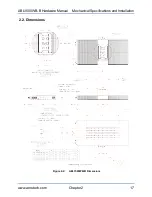
Page 17: ...ABL1500WB B Hardware Manual Mechanical Specifications and Installation 2 2 Dimensions Figure 2 2 ABL1500WB B Dimensions www aerotech com Chapter 2 17 ...

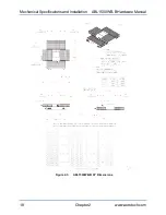
Page 18: ...Mechanical Specifications and Installation ABL1500WB B Hardware Manual Figure 2 3 ABL1500WB B XY Dimensions 18 Chapter 2 www aerotech com ...

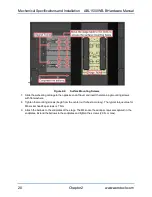
Page 19: ...ss prior to stage assembly at the factory If machining is required to achieve the desired flatness it should be performed on the mounting surface rather than the stage base Shimming should be avoided if possible If shimming is required it should be minimized to improve the rigidity of the system Procedure for ABL1500WB B mounting W A R N I N G Do not attempt to move the carriage of the ABL1500WB B...

Page 20: ...ining mounting screws with flat washers 8 Tighten the mounting screws begin from the center out for best accuracy The typical torque value for M6 socket head cap screws is 7 N m 9 Attach the bellows to the endplates of the stage The M4 socket head cap screws are captured in the endplates Extend the bellows to the endplates and tighten the screws 2 0 N m max 20 Chapter 2 www aerotech com ...

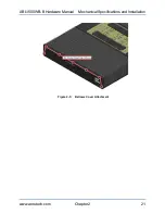
Page 21: ...ABL1500WB B Hardware Manual Mechanical Specifications and Installation Figure 2 5 Bellows Cover Attachment www aerotech com Chapter 2 21 ...

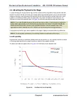
Page 22: ...trols it might have been tuned with a representative payload based on the information provided at the time of order If the ABL1500WB B is started up without a payload the servo gains provided by Aerotech with the shipment may not be appropriate and servo instability can occur Refer to the controller help file for tuning assistance The payload must be flat rigid and comparable to the stage in quali...

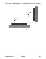
Page 23: ...ABL1500WB B Hardware Manual Mechanical Specifications and Installation Figure 2 7 Cantilever Length Diagram www aerotech com Chapter 2 23 ...

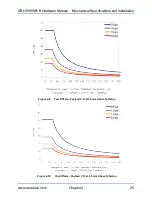
Page 24: ...on possible for the ABL1500WB B series stages is 2g Figure 2 8 shows allowable payload and center of gravity locations with respect to the table top for laterally centered loads Figure 2 9 and Figure 2 10 show the allowable payload and lateral center of gravity offset for a payload whose center of gravity is located 25 mm and 50 mm above the stage table top respectively Figure 2 8 Pitch Offsets Va...

Page 25: ...B B Hardware Manual Mechanical Specifications and Installation Figure 2 9 Yaw Offsets Payload C O G 25 mm Above Tabletop Figure 2 10 Yaw Offsets Payload C O G 50 mm Above Tabletop www aerotech com Chapter 2 25 ...

Page 26: ...Mechanical Specifications and Installation ABL1500WB B Hardware Manual 26 Chapter 2 www aerotech com This page intentionally left blank ...

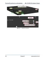
Page 27: ... to the sections that follow for standard motor wiring and connector pinouts The stage and its carriage are protected from dangerous faults by an integral safety ground through the stage s motor power cable In addition a spot faced safety ground connection point shown in Figure 3 1 is provided on the stage endplate for customer use W A R N I N G Applications requiring access to the stage while it ...

Page 28: ...Electrical Specifications and Installation ABL1500WB B Hardware Manual Figure 3 1 Connector Locations 28 Chapter 3 www aerotech com ...

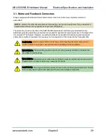
Page 29: ...ator or qualified installer is responsible for determining and meeting all safety and compliance requirements necessary for the integration of this stage into the final application D A N G E R Remove power before connecting or disconnecting electrical components or cables Failure to do so may cause electric shock or damage to the equipment W A R N I N G The protective ground connection must be pro...

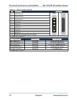
Page 30: ... Reserved 5 Reserved A4 Frame ground motor protective ground 1 Available with Y CMS option Mating Connector Aerotech P N Third Party P N Base Backshell ECK00656 Amphenol 17E 1726 2 Base Sockets QTY 4 ECK00659 ITT Cannon DM53744 6 Base Connector ECK00657 ITT Cannon DBM9W4SA197 Carriage Backshell 1 ECK00656 Amphenol 17E 1726 2 Carriage Connector 1 ECK00101 FCI DB25P064TXLF 1 Available with Y CMS opt...

Page 31: ...ved 14 Cosine 15 Cosine N 16 5 V power supply 17 Sine 18 Sine N 19 Reserved 20 Limit Common 21 Encoder Common 22 Reserved 23 Reserved 24 2 Signal indicating maximum travel produced by negative CCW stage direction 25 Reserved Case Signal shield connection to case 1 Available with Y CMS option 2 For limit information on stages shipped with the E3 option refer to Section 3 3 1 Mating Connector Aerote...

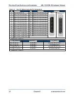
Page 32: ... O 18 8 Amp max 7 User I O 6 8 Amp max 20 User I O 19 8 Amp max 8 User I O 7 8 Amp max 21 User I O 20 8 Amp max 9 User I O 8 8 Amp max 22 User I O 21 8 Amp max 10 User I O 9 8 Amp max 23 User I O 22 8 Amp max 11 User I O 10 8 Amp max 24 User I O 23 8 Amp max 12 User I O 11 8 Amp max 25 User I O 24 8 Amp max 13 User I O 12 8 Amp max 1 Available with Y CMS option Mating Connector Aerotech P N Third ...

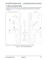
Page 33: ...rers have their own designations for motor phases A B C and Hall signals A B C refer to Section 3 5 for motor phasing Shielded cables are required for the motor and feedback connections See Section 3 3 1 for limit information on stages shipped with the E3 encoder option Figure 3 2 Motor and Feedback Wiring www aerotech com Chapter 3 33 ...

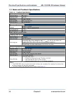
Page 34: ... Ω Load differential signals SIN SIN COS COS are 5 V pk pk relative to ground Digital Output Incremental Encoder RS422 485 compatible Limit Switch Specifications Supply Voltage 5 V from encoder Supply Current 250 mA typical Output Type Open Collector Output Voltage 24 VDC max through pull up resistor Output Current 20 mA max sinking Output Polarity Normally Closed NC l Sinks current to ground Logi...

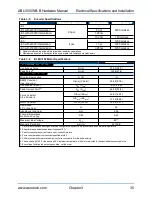
Page 35: ...stant line line max V m s V in s 30 66 0 78 Continuous Current Apk Arms 8 00 5 66 Peak Current Stall 3 Apk Arms 46 40 32 8 Force Constant Sine Drive 4 5 N Apk lb Apk 26 67 6 00 N Arms lb Arms 37 72 8 48 Motor Constant 4 6 N W lb W 14 56 3 27 Resistance 25 C line line Ω 3 2 Inductance line line mH 0 95 Thermal Resistance No Forced Cooling C W 0 47 Maximum Bus Voltage VDC 80 7 Magnetic Pole Pitch mm...

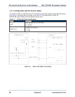
Page 36: ...ble of sinking 8mA Table 3 7 describes these two signals As in Figure 3 3 if the LIMIT signal is HIGH the DIRECTION signal indicates which end of travel limit is active Table 3 7 E3 Encoder Option Limit Signals Signal Description LIMIT EOT Limit indicator non directional 0 No Limit 1 In Limit DIRECTION LIMIT Directional Signal 0 CW 1 CCW Figure 3 3 E3 Encoder Option Limit Wiring 36 Chapter 3 www a...

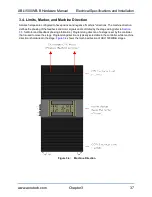
Page 37: ...back and motor signals and is dictated by the stage wiring refer to Section 3 5 for Motor and Feedback phasing information Programming direction of a stage is set by the controller that is used to move the stage Programming direction is typically selectable in the controller while machine direction is hardwired in the stage Figure 3 4 shows the machine direction of ABL1500WB B stages Figure 3 4 Ma...

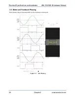
Page 38: ...ecifications and Installation ABL1500WB B Hardware Manual 3 5 Motor and Feedback Phasing Motor phase voltage is measured relative to the virtual wye common point Figure 3 5 Hall Phasing 38 Chapter 3 www aerotech com ...

Page 39: ...L1500WB B Hardware Manual Electrical Specifications and Installation Figure 3 6 Analog Encoder Phasing Reference Diagram Figure 3 7 Encoder Phasing Reference Diagram Standard www aerotech com Chapter 3 39 ...

Page 40: ...Electrical Specifications and Installation ABL1500WB B Hardware Manual 40 Chapter 3 www aerotech com This page intentionally left blank ...

Page 41: ...l Visually inspect the stage and cables l Re tighten loose connectors l Replace or repair damaged cables l Clean the ABL1500WB B and any components and cables as needed l Repair any damage before operating the ABL1500WB B l Inspect and perform an operational check on all safeguards and protective devices 4 2 Cleaning and Lubrication You must periodically re lubricate the bellows Lubricating the be...

Page 42: ...imize the possibility of bodily injury or death disconnect all electrical power prior to performing any maintenance or making adjustments to the equipment 2 Unbolt the bellows from both endplates Clean all of the surfaces that you can access Make sure to use the correct solvent on each surface refer to Section 4 2 When the surface is fully dry move the stage by hand to the opposite end of travel W...

Page 43: ...ng the stage see Section 4 2 1 Begin by removing power from the stage Unbolt the bellows from the stage endplates Move the stage carriage to one end of travel and compress the bellows Clean the bellows track with Acetone to remove any leftover grease After the solvent has dried brush new grease onto the track Aerotech recommends NSK LGU grease Move the stage carriage to the opposite end of travel ...

Page 44: ...t The system is configured to operate with an air pressure safety switch and either the air pressure is too low or the switch is not present Check the air supply and the switch Air pressure switches are typically configured to trip if the supply pressure to the bearing drops below 40 psi Stage moves uncontrollably l Encoder sine and cosine signal connections refer to Chapter 3 and Controller docum...

Page 45: ...ut such approval A Return Materials Authorization RMA number must accompany any returned product s The RMA number may be obtained by calling an Aerotech service center or by submitting the appropriate request available on our website www aerotech com Products must be returned prepaid to an Aerotech service center no C O D or Collect Freight accepted The status of any product returned later than th...

Page 46: ...erms and conditions stated in the following On Site Non Warranty Repair section apply On site Non Warranty Repair If any Aerotech product cannot be made functional by telephone assistance or purchased replacement parts and cannot be returned to the Aerotech service center for repair then the following field service policy applies Aerotech will provide an on site Field Service Representative in a r...

Page 47: ...ision History Revision General Information 1 02 00 l Safety information updated l General revision l Stage Mass updated Section 1 3 l Motor Feedback connector keying updated 1 01 00 Limit operation section added 1 00 00 New Manual www aerotech com Appendix B 47 ...

Page 48: ...Revision History ABL1500WB B Hardware Manual 48 Appendix B www aerotech com This page intentionally left blank ...

Page 49: ...ll Effect Sensors Specifications 34 hose air 14 Humidity 12 I Inspection Schedule 41 Isopropyl Alcohol 41 L label 15 lifting bars 15 Lifting Hardware 15 Limit Switch Specifications 34 Lubrication 41 M MCA03094 14 mounting surface securing stage 19 P part number 15 pressure switch 14 Protection Rating 12 protective ground connection 29 S Securing the Stage to the Mounting Surface 19 serial number 1...

Page 50: ...Index ABL1500WB B Hardware Manual Thermistor Specifications 34 V Vibration 12 W Warranty and Field Service 45 50 Index www aerotech com ...

Reviews: