background image


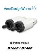
operating manual B100F / B140F 2019-06-27 

manufacturer’s specifications. 

  The turbine must be installed in a way that it can be cooled by 

a bypassing air stream. 

  Combustible liquids and gases as well as tanks and tubes must 

be kept or installed in safe distance of the engine. 

  The  intake  area  (impeller  /  compressor)  must  be  kept  clear. 

Any wires, tubes, etc. must be installed and fixed in a way they 
cannot be sucked into the turbine. In general, there should not 
be  any  objects  or  installations  close  to  the  front  end  of  the 
turbine. 

  The intake section of the model should have at least twice the 

area of the impeller/compressor wheel. 

  You must make sure that no objects, e.g. rocks, dirt, screws, 

etc., can be sucked into the turbine. It is a good idea to protect 
the turbine intake with a close meshed screen (accessories). 

  The intake area must be absolutely kept clear. 


2.3.  Assembly of the complete system 


  Please  look  at  the  installation  scheme  as  well  as  the 

illustration. 

  The optimum size of the fuel tank depends on the model but 

should be at least 1.7 liters. The optimum size for the B100F / 
B140F


 is 2 - 3 liters, which is enough for an average air time 

of 6 – 8 minutes, depending on your style of flying. For further 
information please see technical data, fuel consumption. There 
must be a 

felt pendulum

 in the tank. Use only the included felt 

pendulum. 
The tank set up can be realized with a so called Hopper tank 
(please see installation scheme “engine fuel supply”. The felt 
pendulum only can be installed in the Hopper tank; there 

must


be  a  free  passage  to  the  other  tanks  of  3  mm  diameter 
(minimum). 
Use yellow, highly flexible Tygon tube and attach it to the pump 
with a cable connector. Tank accessories, pendula, etc. can be 
found in the AeroDesignWorks line up. 

  The fuel pump must be installed directly 

behind

 the tank. Be 

careful to install the pump correctly (brass fitting = draw side). 
The electric wiring of the pump has to be done with the correct 
polarity 

(+ / -)

. If the pump is not wired correctly, it will not work 

right and will transport no fuel 

  Install the fine filter in the pressure tube 

behind 

the fuel pump 

Summary of Contents for B100F

Page 1: ...operating manual B100F B140F...

Page 2: ...Directions for safe operation 1 1 General safety instructions 1 2 Warning 1 3 Before starting the turbine 1 4 During operation 1 5 After shut off 2 Mounting of the engine 2 1 Mounting options 2 2 Saf...

Page 3: ...sile loads and temperatures Therefore it cannot be excluded that parts of failing turbine fan wheels and broken fans will strike through the housing which can lead to damage and even injury or death S...

Page 4: ...is device must read this manual especially the instructions for safe operation Furthermore one has to follow the laws and general rules of the avoiding of accidents technical safety as generally valid...

Page 5: ...ngine Really make sure to first inform then buy have the fitting size model for your turbine select servos that are powerful enough construct servo wiring and rudder joints very carefully and reinforc...

Page 6: ...nto the jet exhaust Severe burns can be the result 1 5 After shutting off the engine Place model with the nose facing the wind Wait until the cooling down process is completed Be aware of the cooling...

Page 7: ...led in a way that the area between ignition plug and cerosin plug is in the 12 o clock position see picture This is absolutely vital for a kerosine start of the B100F B140F engine Else the start i e t...

Page 8: ...illustration The optimum size of the fuel tank depends on the model but should be at least 1 7 liters The optimum size for the B100F B140F is 2 3 liters which is enough for an average air time of 6 8...

Page 9: ...perfectly locked in For release push the blue cap in the direction of the metal piece and remove the tube by pulling Now the turbine should be electrically wired to the ECU Connect the turbine via hig...

Page 10: ...8 activate manual point 2 1 Abgleich adjustment trim and throttle back Enter trim forward Enter Throttle forward Enter Sender is now adjusted Make sure that no sender functions like Dual Rate Expo dis...

Page 11: ...controlled with the throttle All parameters necessary for operation are now controlled Failure of the turbine or the system are now excluded Conduct a test run of your turbine and also test the range...

Page 12: ...U features a CODE controlled menu system Every number features an individual menu point From these menu points you have options of changing different pre set parameters This should if at all be done v...

Page 13: ...mpensation of any kind unless regulated differently by law This includes injury death material damage loss of profit or business interruption of business and other directly or indirectly resulting con...

Page 14: ...changed after 10 hours of operation The upstream fine filter between pump and turbine should be cleaned every 5 hours of operation Do this very carefully and make sure no particles will enter the fue...

Page 15: ...faults 24 months from the date of purchase Further liability is excluded Any costs caused by transport and packaging have to be paid by the customer There is no liability of AeroDesignWorks GmbH conce...

Page 16: ...nds acceleration 50 125 000 rpm 1 0 seconds maintenance interval every 50 hours earlier in case of bearing noise or other reasons B140F diameter 99 0 mm length 296 0 mm weight ca 1240 g max thrust 128...

Page 17: ...operating manual B100F B140F 2019 06 27 16 8 System installation plan system installation plan for fuel start...

Page 18: ...ser See technical data fuel consumption Usually 2 3 liter tanks are used with B100F B140F turbines Drill a 6 mm hole in the fuel tank cap of your choice Use the included tank pendulum device and screw...

Page 19: ...body Then secure the Tygon tube connections with wire Again check for leak tightness Braze the battery cable to your chosen battery Red plus black minus We recommend 3s LiPo batteries with max 12V and...

Page 20: ...your model the diameter of the extension pipe and the distance from nozzle to nozzle extension must be correct The shorter the nozzle extension the smaller the loss of power The extension pipe must b...

Page 21: ...B140F 2019 06 27 20 Thank you for your attention Your team of AeroDesignWorks GmbH Wankelstr 57 50996 K ln Tel 49 0 221 984311 50 Fax 49 0 221 984311 02 www aerodesignworks com thrust turbines turbin...

Reviews:

Related manuals for B100F