Heat recovery units with refrigeration circuit -
URX_CF
-
25
Selection and installation manual
GB
The assembly of the "free-cooling kit"
accessory must be performed by qualified
personnel in accordance with the present
standards and must be made following the
indications in the electrical layout supplied
with the unit.
The compressor is off during the
functioning of the unit in the free-cooling
mode. The temperature settings are pre-set
at fixed values (on request these values can
be changed by contacting the After-Sales
office).
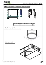
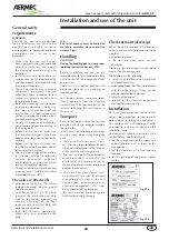
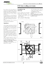
See the indications in fig. 12 for the
installation of the free-cooling kit.
Operation
The free-cooling function foresees that the
air expelled from the room does not affect
the heat recovery unit, passing directly to
the outside through a duct connected to
the damper B.
Thus, the fresh air flow passes through the
filter and the heat recovery unit without
being touched by the heat recuperator.
In order to use the free-cooling function a
duct is required to connect to damper A
and another to connect to damper B. The
two dampers A and B have an opposing
function.
When the outside temperature is close to
the ideal temperature of the room, damper
A is closed while damper B is open.
Damper A can be positioned on the side
as indicated in the line diagram.
The compressor is off when the unit is
operating in free-cooling.
Assembly of the
accessory
For the assembly of the free-cooling
accessory please refer to fig. 12 and 13
• p l a c e t h e t wo d a m p e r s w i t h
servomotors MES and MESF as in the
previous diagram;
• make sure that the damper with the
MES servomotor is closed during
the free-cooling function while the
damper with the MEFS servomotor is
open (opposing functions);
• connect the damper servomotors;
CAUTION!
Before assembling the free-cooling
kit, make sure that the power is not
connected to the unit.
FCE free-cooling accessory
Damper A
Damper B
EXTERNAL
INTERNAL
Exhaust damper
actuator
EXTERNAL
INTERNAL
Outside air
temperature
probe already
present
Free-cooling
Damper actuator
Room temperature
probe already present
MES
BTR
MESF
BTE
fig.12
fig.13
Summary of Contents for URX CF
Page 2: ......
Page 31: ...NOTE ...
Page 32: ...NOTE ...
Page 33: ...NOTE ...
Page 34: ...NOTE ...
Page 35: ......


