background image

Heat recovery units with refrigeration circuit - 

URX_CF

 -

20

Selection and installation manual 

GB

SUF, MBC, MBX 

and RBX

 assembly

Accessories MBC, MBX, 

RBX and

 SUF 

are equipped with:
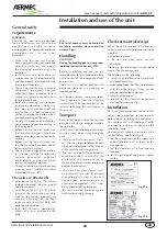
-  “L” supporting brackets;
- a flange for the accessory connection 
to the unit;
- a flange for the accessory connection 
to the ducts.
- viti M6 screws to tighten the accessory 
to the unit;
- only for MBX 

and RBX

: electrical box 

put outside the accessory;
- only for MBC:  electrical cables for 
connection between three way valve 
servocontrol (230V, ON/OFF running) 
and electrical box and between electri-

cal box and unit electrical panel; 
- only for MBX 

and RBX

: electrical 

cables for connection between coil and 
electrical box and between electrical 
box and unit electrical panel (electrical 
cables for coil electrical supply and 
protection differential magnetic switch 
are not supplied).  

Fot accessories installation on the cei-
ling  and their connection to the unit 
please refer to the following instructions:
- position the support brackets on the wall 
following the instructions at page 24;

- unscrew totally the screws form the 
unit in correspondance of the holes 
which couples with accessory flange; 
- draw the accessory MBC, MBX, 

RBX 

and 

SUF to the unit;

- screw the screws previously unscre-
wed and by screws equipped with the 
accessory, the accessory and its flan-
ge to the unit prepared with threaded 
hexagonal inserts;
- connect electrical cables coming from 
the accessory electrical box to the unit 
electrical panel (please refer to electri-
cal schemes equipped with the unit).

Summary of Contents for URX CF

Page 1: ...URX_CF EN HEAT RECOVERY UNITS WITH REFRIGERATION CIRCUIT SELECTION AND INSTALLATION MANUAL 0313 6180417_03 ...

Page 2: ......

Page 3: ...ency Pressure drop air side accessories MBC SUF 13 Refrigerating circuit 14 Dimensions 15 Accessories Dimensions 18 Installation and use of the unit 22 Positioning of the supporting brackets 23 Connection of ducts 24 Hydraulic connections of the condensate drain 24 FCE free cooling accessory 25 Electrical connections 26 Maintenance of the unit 27 Filters 27 Condensate drain pan 27 Heat recovery 27...

Page 4: ...tograms on the machine which help understand the manual better rapidly catching the attention of the reader concerning the risks which can not be avoided or sufficiently limited through the use of technical protection means and measures GENERAL HAZARD SIGNAL Carefully adhere to all the indications next to the icon Failure to comply with the instructions may generate hazardous situations with possi...

Page 5: ...e design of the machine combines the extremely compact size which makes installation on suspended ceilings easier with easy accessibility for the maintenance of all internal parts This gives the opportunity also thanks to the management and installation simplicity to satisfy many system requirements WARNING The URX_CF series is made to guaran tee indoor air supply and extraction The refrigerating ...

Page 6: ...to the electronic controllers for the detection of the choking of the supply filter It is possible to set the intervention value Thre pressure switch includes clean contacts NA NC to remote the alarm Heat recovery unit this is static with crossflow made of aluminium sheets During winter operation the average efficiency is above 50 ensuring first class energy recovery from the air expelled from the...

Page 7: ...am from the motor fan assembly on the fresh air flow fitted with Electrical resistance in two stage finned armored elements with double safety thermostat with automatic reset and manual G4F G4 efficiency filters The units can be fitted with two cell type filters with corrugated septum in class G4 according to the UNI EN 779 classification weighted efficiency of 90 which can be placed as a replacem...

Page 8: ...2 3 3 0 4 8 5 2 Refrigerating available capacity 2 kW 1 4 1 7 2 2 3 4 5 1 Recovered heating capacity 3 kW 2 9 4 3 7 1 10 1 14 3 Recovered refrigerating capacity 2 kW 0 9 1 3 2 0 2 8 4 2 Compressor heating capacity 3 kW 5 9 6 5 8 7 12 7 19 0 Compressor refrigerating capacity 2 kW 5 2 6 0 8 2 12 2 18 8 Total input power Heating mode 3 kW 2 0 2 0 3 3 4 0 5 5 Total input power Cooling mode 2 kW 2 6 2 ...

Page 9: ...763 902 1475 Water side pressure drop 1 kPa 16 22 9 12 31 Water flow rate 2 l h 336 382 584 638 1306 Water side pressure drop 2 kPa 11 14 6 7 28 MBX Electric heating coil Alimentation 3 ph 400 V 50 Hz separate power supply from the unit Heating capacity kW 3 0 4 5 6 0 9 0 12 0 Air side pressure drop at nominal flow rate Pa 10 10 10 10 10 Stages n 1 1 1 1 1 Electric heating element current input A ...

Page 10: ... Total dB dB dB dB dB dB dB dB dB dB A dB A 07 56 55 51 50 49 44 40 33 60 53 64 10 59 60 54 52 50 45 41 35 64 55 66 15 62 65 57 54 51 47 42 36 68 57 68 21 64 69 60 55 52 48 43 38 71 59 70 33 67 74 63 57 53 49 44 39 75 62 73 63 125 250 500 1000 2000 4000 8000 Sound pressure dB dB dB dB dB dB dB dB dB dB A 07 65 57 54 57 54 50 53 48 67 0 60 10 66 58 56 60 57 57 57 52 68 8 64 15 67 59 58 62 60 61 63 ...

Page 11: ... static head 206 Pa It is supposed that the pressure drops of the air distribution system on the supply side are equal to 210 Pa while the pressure drops of the air distribution system on the exhaust side are equal to 180 Pa Fans available static pressure The Effective useful pressure Nominal useful pressure reports are 210 223 0 94 and 180 206 0 87 respectively The coefficients that can be taken ...

Page 12: ...0 90 40 2 53 1 26 3 44 Winter use X T ext Y media ΔT Q nom Q nom 15 Q nom 15 5 0 00 3 02 1 84 0 2 73 5 25 0 26 5 5 56 8 27 3 07 10 8 67 11 53 6 38 15 11 89 14 58 9 36 20 15 09 18 03 12 70 7 6 5 4 3 2 1 0 1 2 3 4 5 25 26 27 28 29 30 31 32 33 34 35 36 37 38 39 REGIME ESTIVO Qnom Qnom 15 Qnom 15 Variation of the inlet air temperature C Summer use Winter use Variation of the inlet air temperature C Ex...

Page 13: ...r to multiply for the nominal capacity value are present in the technical data table Fig 07 illustrates the pressure drops Pa on the air side based on the flow rate for the MBC and SUF accessories Fig 08 illustrates the pressure drops kPa water side of the MBC accessory coil N B The pressure drops illustrated in the diagram also include those of the three way valve fig 06 External air temperature ...

Page 14: ...il BE Evaporating coil VME Summer supply fan VMI Winter supply fan SL Liquid separator VU One way valve IL Liquid indicator F Filter VE Thermostatic valve RL Liquid receiver PA High pressure probe VIC Valvola inversione di ciclo AP High pressure switch BP Low pressure switch SV Solenoid valve Only present in 07 and 10 models Only present in 07 model ...

Page 15: ...CF Weights and centres of mass kg Gx Gy URX07CF 205 700 650 URX10CF 218 700 650 Supply fan Exhaust fan By pass for free cooling External air suction External air suction Expulsion of exhaust air or inspection of refrigerating circuit Electric panel Expulsion of exhaust air or inspection of refrigerating circuit h 5 X Y ...

Page 16: ...ights and centres of mass kg Gx Gy URX15CF 272 800 750 URX21CF 298 760 750 Supply fan Exhaust fan By pass for free cooling External air suction External air suction Expulsion of exhaust air or inspection of refrigerating circuit Electric panel Expulsion of exhaust air or inspection of refrigerating circuit X Y 999 6 ...

Page 17: ...3CF Weights and centres of mass kg Gx Gy URX33CF 328 850 800 Supply fan Exhaust fan By pass for free cooling External air suction External air suction Expulsion of exhaust air or inspection of refrigerating circuit Electrical panel Expulsion of exhaust air or inspection of refrigerating circuit X Y 1011 ...

Page 18: ...pection panel set 2 Lower panel bdampering profile 3 Upper fixing bracket 4 Silencer 5 Baffles fixing bracket 6 Duct accessories connection flange G D C M I H I M B Mod mm URX_CF 07 10 URX_CF 15 21 URX33CF A 600 600 600 B 835 835 835 C 400 500 550 D 30 30 30 E 31 5 31 5 31 5 F 537 537 537 G 337 437 487 H 490 490 490 I 50 50 50 L 632 632 632 M 108 108 108 ...

Page 19: ...D B I M H I M Mod mm URX_CF 07 10 URX_CF 15 21 URX33CF A 600 600 600 B 435 435 435 C 400 500 550 D 30 30 30 E 31 5 31 5 31 5 F 537 537 537 G 337 437 487 H 250 250 250 I 50 50 50 L 632 632 632 M 28 28 28 N 40 40 40 O 85 85 85 P 278 278 278 Q 127 127 127 MBC Water coil modules MBX RBX MBX Electrical coil modules RBX Preheating Electrical coil modules ...

Page 20: ...nd electrical box and between electrical box and unit electrical panel electrical cables for coil electrical supply and protection differential magnetic switch are not supplied Fot accessories installation on the cei ling and their connection to the unit please refer to the following instructions position the support brackets on the wall following the instructions at page 24 unscrew totally the sc...

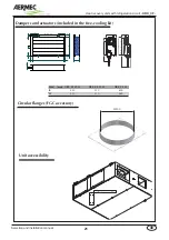
Page 21: ...cuit URX_CF 21 Selection and installation manual GB 380 mm Unit accessibility Circular flanges FGC accessory Mod mm URX_CF 07 10 URX_CF 15 21 URX_CF 33 B 450 550 600 H 310 410 460 ORI MM O Dampers and actuators included in the free cooling kit ...

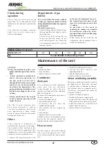
Page 22: ...re performing maintenance or cleaning operations make sure that the unit is disconnected and ensure that it is not reconnected without informing the person who is presently working on the unit During maintenance and cleaning pay attention to possible burning of the heating coils Before starting the unit make sure that the electrical parts have been connected to the earth system of the building Bef...

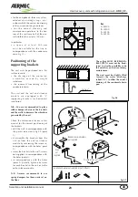
Page 23: ...ons generated by the unit Check the dimensional layout in this manual for the correct positioning of the brackets drill the wall in correspondence with the points indicated in fig 09 point 1 disassemble the brackets from the unit or from the coil or silencer module by unscrewing the screws in correspondence with the holes point 2 screw the brackets to the wall screws not supplied in correspondence...

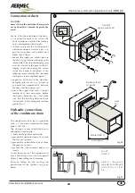
Page 24: ...ntee the unipotentiality between the ducts and the recovery unit place the supply duct with a straight section of at least one meter before the bends branches etc and make sure that the ductling does not have inclinations of the divergent sections greater than 7 Hydraulic connections of the condensate drain The condensate drain pan is provided with a 1 diameter threaded discharge pipe G UNI 338 Th...

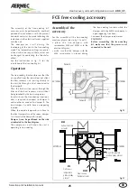
Page 25: ... the free cooling function a duct is required to connect to damper A and another to connect to damper B The two dampers A and B have an opposing function When the outside temperature is close to the ideal temperature of the room damper A is closed while damper B is open Damper A can be positioned on the side as indicated in the line diagram The compressor is off when the unit is operating in free ...

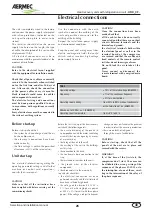
Page 26: ...board Before start up Before start up check that the system has been charged and the air has been blown out the electrical connections have been made correctly the line voltage is within the permitted allowance 10 of the rated value Unit start up For detailed information regarding the operating parameter settings and all other machine or control card operations consults the user manual CAUTION Mak...

Page 27: ...n be cleaned with a jet of compressed air or cold water To disassemble the heat recovery unit remove the condensate drain pan remove the heat recovery unit supporting brackets clean the heat recovery unit replace all parts in reverse order Motor ventilating assembly The motor ventilating assembly needs to be checked to see how clean the rotor is whether there is corrosion or damage and whether the...

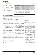
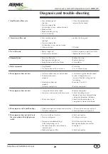
Page 28: ...nd of the useful life as municipal waste but to send it to a special collection center The units covered by the RAEE Directive are marked with the symbol shown above The potential effects on the envi ronment and human health are detailed in this manual Additional information can be obtained from the manufacturer DIAGNOSIS AND TROUBLE SHOOTING Fault finding All units are checked and tested at the f...

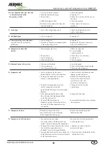
Page 29: ... contacts open Check the voltage and close the contact Thermostat does not System at temperature no respond request check the setting and the functioning Safety device does not See point 9 and 10 respond Defective compressor Replace compressor 7 The compressor does not start Compressor burnt out or seized Replace compressor Compressor remote control switch de energised Check the voltage across the...

Page 30: ...nt 16 Evaporator coil Lack of refrigerant in the circuit Check for leaks and eliminate them before bubbles visible in the indicator topping up with refrigerant Thermostatic expansion valve over Reduce the overheating of the closed suction pipe too hot thermostatic expansion valve turn the valve stem and check the suction pressure Thermostatic expansion valve over Change the valve or free the close...

Page 31: ...NOTE ...

Page 32: ...NOTE ...

Page 33: ...NOTE ...

Page 34: ...NOTE ...

Page 35: ......

Page 36: ...he right to introduce at any time whatever modifications deemed necessary to the improvement of the product 35040 Bevilacqua Vr Italy Via Roma 996 Tel 39 0442 633111 Fax 39 0442 93730 39 0442 93566 http www aermec com carta reciclata recycled paper papier recyclé recycled papier ...

Reviews: